Liquid nitrogen (LN₂) is the lifeblood of modern industry, enabling everything from the flash-freezing of gourmet meals to the cryopreservation of biological samples and the shrink-fitting of aerospace components. For facilities with large, consistent demand, the traditional model of purchasing LN₂ from external suppliers—with its volatile pricing, logistical complexities, and delivery dependencies—becomes a significant operational bottleneck and cost center.
This is where the concept of on-site liquid nitrogen generation transforms from an exotic idea into a strategic asset. An industrial liquid nitrogen generator, often referred to as a liquefier or small-scale air separation plant, allows a facility to produce its own LN₂ directly from the atmosphere. But how exactly can a machine turn the air we breathe into -196°C liquid? This guide demystifies the complete cryogenic process, from intake air to stored liquid, and explores why this capability is a game-changer for high-volume users.
The Core Principle: Cryogenic Air Separation
The fundamental science behind all liquid nitrogen production is cryogenic air separation. The goal is to cool atmospheric air to such extremely low temperatures that it becomes a liquid, and then separate its components—primarily nitrogen (78%), oxygen (21%), and argon (0.9%)—by exploiting their different boiling points.
- Nitrogen (N₂): Boils at -196°C (-320°F)
- Oxygen (O₂): Boils at -183°C (-297°F)
- Argon (Ar): Boils at -186°C (-303°F)
This 13°C difference between the boiling points of oxygen and nitrogen is the key that allows for their separation through a process called fractional distillation. An industrial LN₂ generator is essentially a highly refined, continuous distillation column operating at cryogenic temperatures.
The Step-by-Step Process of an Industrial LN₂ Generator
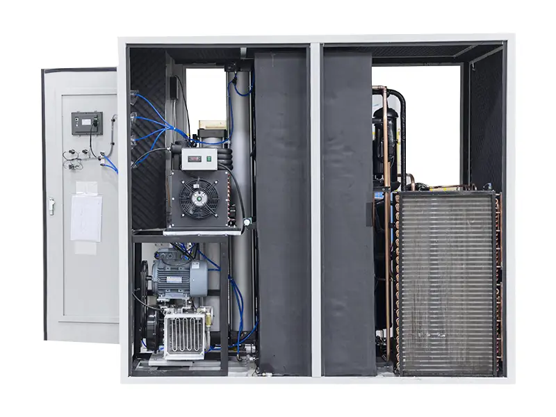
An on-site liquefaction plant is a complex integration of mechanical, thermal, and control systems. Here is the complete journey of air becoming liquid nitrogen:
1. Air Intake, Compression, and Purification
- Intake: Ambient air is drawn through a filter to remove particulates.
- Compression: A multi-stage centrifugal or screw compressor increases the air pressure typically to 5-10 bar (70-150 psi). Compression is essential because it raises the air’s dew point, making subsequent cooling and purification more efficient. It also provides the energy needed to drive the entire cryogenic cycle.
- Purification: The compressed air is critically cleaned. It passes through:
- A refrigerant dryer to remove bulk water vapor.
- A molecular sieve purification system to adsorb remaining water vapor, carbon dioxide (CO₂), and hydrocarbons. These impurities must be removed to absolute trace levels, as they would freeze solid in the cryogenic heat exchangers, causing blockages and operational failure.
2. Heat Exchange and Precooling
The clean, dry, high-pressure air enters the heart of the system: a multi-stream plate-fin heat exchanger.
- Here, the incoming warm air flows through channels adjacent to channels carrying outgoing, frigid waste gases (oxygen-rich stream and excess nitrogen) and the final product (very cold gaseous nitrogen).
- This counter-current flow allows the cold outgoing streams to precool the incoming air to near its liquefaction temperature (around -170°C to -190°C) with remarkable efficiency, recovering “cold energy” before the waste gases are vented.
3. Refrigeration and Expansion: The Joule-Thomson Effect
To achieve the final temperature drop needed for liquefaction, the system employs an expansion turbine or expansion valve.
- The highly pressurized, precooled air is allowed to expand rapidly through this device. This expansion causes a significant temperature drop—a phenomenon known as the Joule-Thomson effect.
- In more advanced systems, an expansion turbine does work (like driving a generator), extracting energy from the air stream and creating an even more dramatic cooling effect. This is the primary source of “cold production” in the cycle.
4. Distillation and Separation in the Cryogenic Column
The now partially liquefied air (-190°C to -195°C) is fed into a double-column distillation system.
- High-Pressure Column (Lower): The air enters the base of this column. As it rises, it comes into contact with descending liquid. Nitrogen, having a lower boiling point, tends to vaporize and rise as a gas to the top. Oxygen, with a higher boiling point, tends to condense and fall as a liquid to the bottom.
- Low-Pressure Column (Upper): The nitrogen-rich vapor from the top of the high-pressure column is transferred to the bottom of the low-pressure column. Here, further distillation occurs under lower pressure, producing a high-purity (typically 99.5%+) nitrogen vapor at the top. The liquid oxygen from the high-pressure column is also further refined in this upper column.
5. Nitrogen Liquefaction and Subcooling
- The high-purity gaseous nitrogen from the top of the low-pressure column is routed back through the main heat exchanger. As it cools the incoming air (Step 2), it is itself warmed and exits as a cold gas.
- A portion of this cold, high-purity nitrogen stream is diverted, further cooled, and then expanded through a valve into a chamber at very low pressure. This final expansion causes it to condense into liquid nitrogen.
- This LN₂ is then “subcooled” (cooled below its boiling point) to ensure it remains in liquid state when transferred to storage, minimizing flash loss.
6. Storage and Vaporization
- The produced liquid nitrogen flows into a vacuum-insulated storage tank, where it is held at approximately -196°C.
- When process demand requires gaseous nitrogen, the LN₂ is pumped from the tank through an ambient vaporizer (often a finned-tube heat exchanger), where it absorbs heat from the surrounding air and converts back to a high-pressure gas for plant use.
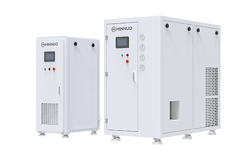
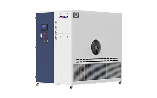
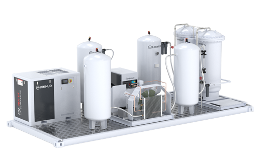
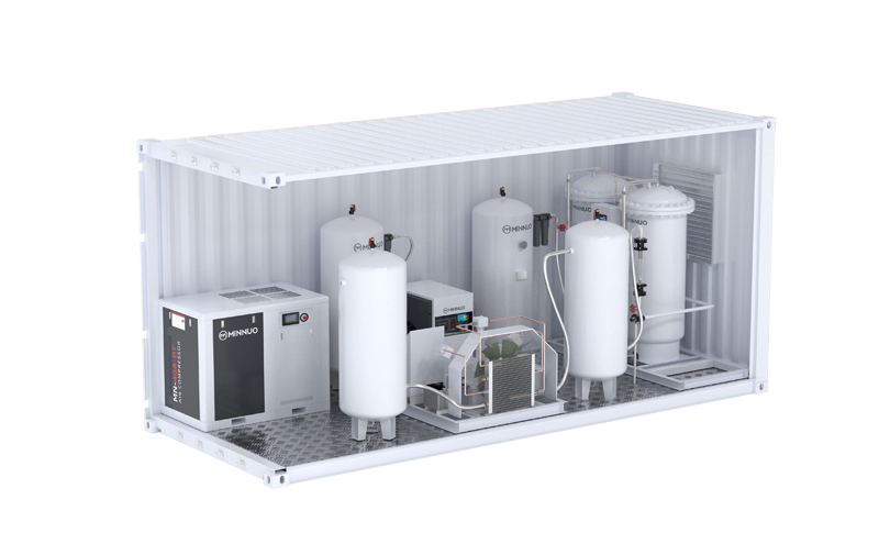
Key Components of an On-Site LN₂ Plant
Understanding the major hardware pieces clarifies the process:
- Air Compressor: Provides the pressurized feed gas.
- Purification Unit (Mole Sieves): The “kidney” of the system, removing impurities.
- Main Heat Exchanger: The “lungs,” enabling efficient heat recovery.
- Expansion Turbine/Valve: The “heart,” creating the cryogenic cooling.
- Distillation Columns (Cold Box): The “brain,” performing the physical separation.
- Liquid Nitrogen Storage Tank (Dewar): The “reservoir” for product.
- Vaporizer and Control System: The “delivery network,” managing output.
On-Site Generation vs. Bulk Delivery: A Strategic Comparison
For the right user, on-site generation offers decisive advantages:
| Consideration | Bulk Liquid Nitrogen Delivery | On-Site Liquid Nitrogen Generation |
| Cost Structure | Variable commodity price + delivery fees + rental fees. | Fixed, predictable cost dominated by capital depreciation and electricity. |
| Supply Security | Vulnerable to logistics, weather, and supplier issues. | Complete independence and 24/7 on-demand production. |
| Purity & Pressure Control | Limited to supplier’s standard. | Fully customizable to your exact process specifications. |
| Ideal User Profile | Low to medium, intermittent consumption. | High-volume, continuous consumers (e.g., >5,000 liters per day). |
| Environmental Impact | High due to transportation and production losses. | Lower; eliminates transport and reduces evaporative losses. |
Major Industrial Applications for Liquid Nitrogen
The unique properties of LN₂—extreme cold and inertness—make it critical for:
- Food Processing: Individually Quick Freezing (IQF) for seafood, fruits, and meat; cryogenic grinding of spices; and modified atmosphere packaging.
- Pharmaceuticals & Biotech: Cryogenic preservation of cells, tissues, and vaccines; inerting for chemical reactions; and cryogenic condensation in lyophilization (freeze-drying).
- Metalworking: Cryogenic treatment of tool steels to enhance wear life; shrink-fitting for assembly; and cryogenic deflashing of molded parts.
- Electronics & Chemicals: Creating inert environments for sensitive production; purging pipelines and reactors.
FAQ
Q1: What is the minimum feasible scale for an on-site LN₂ generator?
A1: While micro-scale units exist, on-site liquefaction becomes economically compelling for facilities with a continuous demand of roughly 5,000 to 10,000 liters of LN₂ per day or more. Below this, the capital investment and operational expertise required often favor bulk supply or on-site gaseous nitrogen generation paired with a small liquefier/refiller.
Q2: How energy-intensive is liquid nitrogen production?
A2: It is a significant energy consumer, as compressing and cooling air to -196°C requires substantial power. Modern plants are designed for high thermodynamic efficiency. The business case is built on replacing the even higher total cost of purchased LN₂ (which includes the supplier’s production energy, profit, and logistics) with your own lower-cost electricity, leading to net savings.
Q3: Is the nitrogen produced on-site of the same quality as purchased LN₂?
A3: Yes, and often better or more consistent. On-site plants can be tuned to produce nitrogen at a specific, guaranteed purity (e.g., 99.9995% for semiconductor use). You control the specification directly, unlike with a delivered product that may vary between batches or suppliers.
Q4: What are the main safety considerations?
A4: Key hazards include asphyxiation (nitrogen displacing breathable air), cryogenic burns from contact with LN₂ or cold surfaces, and pressure hazards. A well-designed installation includes oxygen deficiency monitors, proper ventilation, personal protective equipment (PPE), pressure relief devices, and comprehensive operator training.
Q5: Can we also produce liquid oxygen or argon with such a plant?
A5: Yes. The cryogenic air separation process naturally produces liquid oxygen and liquid argon as co-products. Plants can be designed to be multi-product, yielding LN₂, LOX, and LAR simultaneously, which can improve overall economics if there are local markets for all products.
Conclusion
An industrial liquid nitrogen generator is not merely a piece of machinery; it is a vertically integrated utility plant that confers strategic autonomy. By mastering the cryogenic separation of air, high-volume consumers can break free from the constraints and costs of the liquid gas supply chain, converting a volatile operating expense into a manageable, efficient, and self-controlled production process.
The decision to invest in on-site liquefaction is a significant one, driven by scale, demand stability, and a long-term view on cost control and supply chain resilience. It represents the pinnacle of self-sufficiency in industrial gas supply.
For enterprises where nitrogen is not just a utility but a core component of production, MINNUO offers the engineering expertise, reliable technology, and lifecycle support to assess, implement, and maintain an on-site liquid nitrogen generation system that delivers operational and financial advantages for decades to come.

 sales2:+86 17506119168