In the field of industrial gas production, nitrogen generators have become the core equipment for efficient nitrogen production. The carbon molecular sieve, as the “heart” component responsible for nitrogen-oxygen separation, directly affects production efficiency and cost control. When issues such as leakage and performance degradation occur with the carbon molecular sieve, it not only leads to a decrease in nitrogen purity and a significant increase in energy consumption, but it may also cause equipment damage and safety risks. This article systematically analyzes common failures of carbon molecular sieves, from the principle breakdown to solutions, providing industry users with comprehensive technical guidance.
Common failures of carbon molecular sieves, such as leakage, powdering, and performance degradation, are often caused by poor sieve quality, improper filling processes, or system pressure fluctuations. These failures not only reduce gas production efficiency but may also result in equipment damage and safety hazards. Solutions include molecular sieve testing, intelligent filling, multi-stage filtration, pressure stabilization, online monitoring, and standardized maintenance.
Chapter 1: Overview of Nitrogen Generator Carbon Molecular Sieve Systems
1.1 PSA Nitrogen Generation Technology Principle
Pressure Swing Adsorption (PSA) nitrogen generation technology is a physical process that uses the selective adsorption characteristics of carbon molecular sieves for different components in a gas mixture to achieve nitrogen-oxygen separation under pressure. Its working principle is based on the following two key features:
- Kinetic Diameter Difference: The oxygen molecule (0.346 nm) has a slightly smaller kinetic diameter than the nitrogen molecule (0.364 nm), allowing oxygen to enter the microporous structure of the carbon molecular sieve more quickly.
- Adsorption Rate Difference: Under the same pressure, oxygen diffuses on the carbon molecular sieve 30-50 times faster than nitrogen, allowing oxygen to be preferentially adsorbed during an appropriate adsorption cycle, thereby enriching nitrogen.
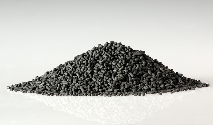
1.2 Structure Characteristics of Carbon Molecular Sieves
High-quality carbon molecular sieves typically exhibit the following structural characteristics:
- Pore Size Distribution: Primarily concentrated between 0.3-0.5 nm. This precise pore size control is the basis for efficient separation.
- Specific Surface Area: Usually between 600-1000 m²/g, providing sufficient adsorption sites.
- Porosity: About 40-50% total pore volume, ensuring good gas diffusion performance.
- Bulk Density: Generally in the range of 0.6-0.7 g/cm³, affecting the design parameters of the adsorption tower.
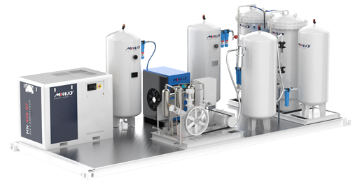
1.3 Typical Nitrogen Generator System Composition
A complete PSA nitrogen generation system typically includes the following core components:
- Air Compression System: Provides compressed air at 0.7-1.0 MPa.
- Air Purification System: Includes a refrigerated dryer, multi-stage filters, and adsorption dryers.
- Adsorption Tower Group: Usually consists of a double tower structure, filled with carbon molecular sieve.
- Pneumatic Valve System: Precisely controls the gas flow and pressure changes.
- Buffer Tank: Stabilizes the nitrogen output pressure.
- Control System: PLC or DCS controls the adsorption cycle and system operation.
Chapter 2: Comprehensive Analysis of Carbon Molecular Sieve Leaks
2.1 Detailed Characterization of Leakage Phenomena
Carbon molecular sieve leakage typically develops progressively and can be divided into three stages:
Early Stage:
- Occasional small black powder in the vent pipe.
- Nitrogen purity fluctuation increases (±1%).
- Minor increase in adsorption tower pressure differential (10-15%).
Mid Stage:
- Continuous appearance of smoke-like particles in the vent pipe.
- Nitrogen purity drops by 2-3 percentage points.
- Noticeable increase in equipment noise.
- Annual sieve wear rate reaches 5-8%.
Severe Stage:
- Obvious particulate carbon molecular sieve ejection.
- Nitrogen purity cannot meet required specifications.
- Increased equipment vibration.
- Mechanical damage to internal components.
2.2 Multidimensional Assessment of Leakage Hazards
2.2.1 Production Efficiency Impact:
- Reduced Nitrogen Yield: For every 1% loss of molecular sieve, the production of nitrogen decreases by approximately 0.8%.
- Increased Energy Consumption: To maintain purity, compressors need to run 15-20% more.
- Downtime Loss: Each major leakage treatment requires 24-72 hours of downtime.
2.2.2 Equipment Damage Assessment:
- Filter Damage: High-speed particle impact causes metal fatigue.
- Valve Wear: Powder entering sealing surfaces accelerates wear.
- Instrument Failure: Probes covered by powder lead to inaccurate measurements.
2.2.3 Safety Hazard Analysis:
- Explosion Risk: In an oxygen-rich environment, carbon powder may form explosive mixtures.
- Environmental Pollution: Emitted molecular sieve particles may violate environmental regulations.
- Health Risks to Personnel: Inhalation of carbon powder may cause respiratory damage.
Chapter 3: In-depth Analysis of Leakage Causes
3.1 Comprehensive Evaluation of Molecular Sieve Quality
3.1.1 Laboratory Testing Indicators
A reputable molecular sieve supplier should provide the following test reports:
| Test Item | Standard Method | Pass Criteria |
| Compressive Strength | ASTM D4179 | ≥60 N/particle |
| Wear Rate | ASTM D4058 | ≤1%/year |
| Adsorption Capacity | ISO 12500 | ≥28 m³N₂/t |
| Moisture Content | GB/T 6284 | ≤1.5% |
| Bulk Density | GB/T 16913 | 0.65±0.05 g/cm³ |
3.1.2 On-Site Quick Identification Methods
In the absence of professional equipment, the following methods can be used for preliminary assessment:
- Appearance Check: High-quality molecular sieve particles are uniform with no significant powder.
- Sedimentation Test: Pour 100 ml of molecular sieve into a graduated cylinder and allow it to settle for 1 hour; the sedimentation rate should be < 5%.
- Strength Test: Randomly take 10 particles and squeeze them with fingers. No more than 2 particles should break.
3.2 Professional Requirements for Filling Process
3.2.1 Standard Equipment for Professional Filling Operations
A professional filling operation should be equipped with:
- Electromagnetic Vibrator: Frequency 50 Hz, amplitude 1-2 mm.
- Grading Sifting Device: Ensures even particle distribution.
- Vacuum Suction System: Prevents dust contamination.
- Density Detector: Monitors filling density in real-time.
3.2.2 Filling Density Control Standards
Recommended filling densities for different sieve types:
| Sieve Type | Recommended Density (g/cm³) | Allowable Deviation |
| Regular Type | 0.65-0.68 | ±0.02 |
| High-Density Type | 0.70-0.73 | ±0.015 |
| Wear-Resistant Type | 0.68-0.71 | ±0.018 |
3.3 Fine Control of Gas Source System
3.3.1 Impact of Pressure Fluctuations
Experimental data show:
- Pressure fluctuation ±0.1 MPa increases wear rate by 25%.
- Pressure fluctuation ±0.2 MPa increases wear rate by 60%.
- Pressure fluctuation ±0.3 MPa increases wear rate by 120%.
3.3.2 Pressure Stabilization Solutions
It is recommended to implement a three-level pressure regulation system:
- Front-end Air Storage Tank: Volume ≥ 1/5 of the compressor’s airflow per minute.
- Precision Pressure Regulator: Accuracy level not lower than 0.5.
- Buffer Device: Add a buffer tank before the adsorption tower.
Chapter 4: Integrated Solutions
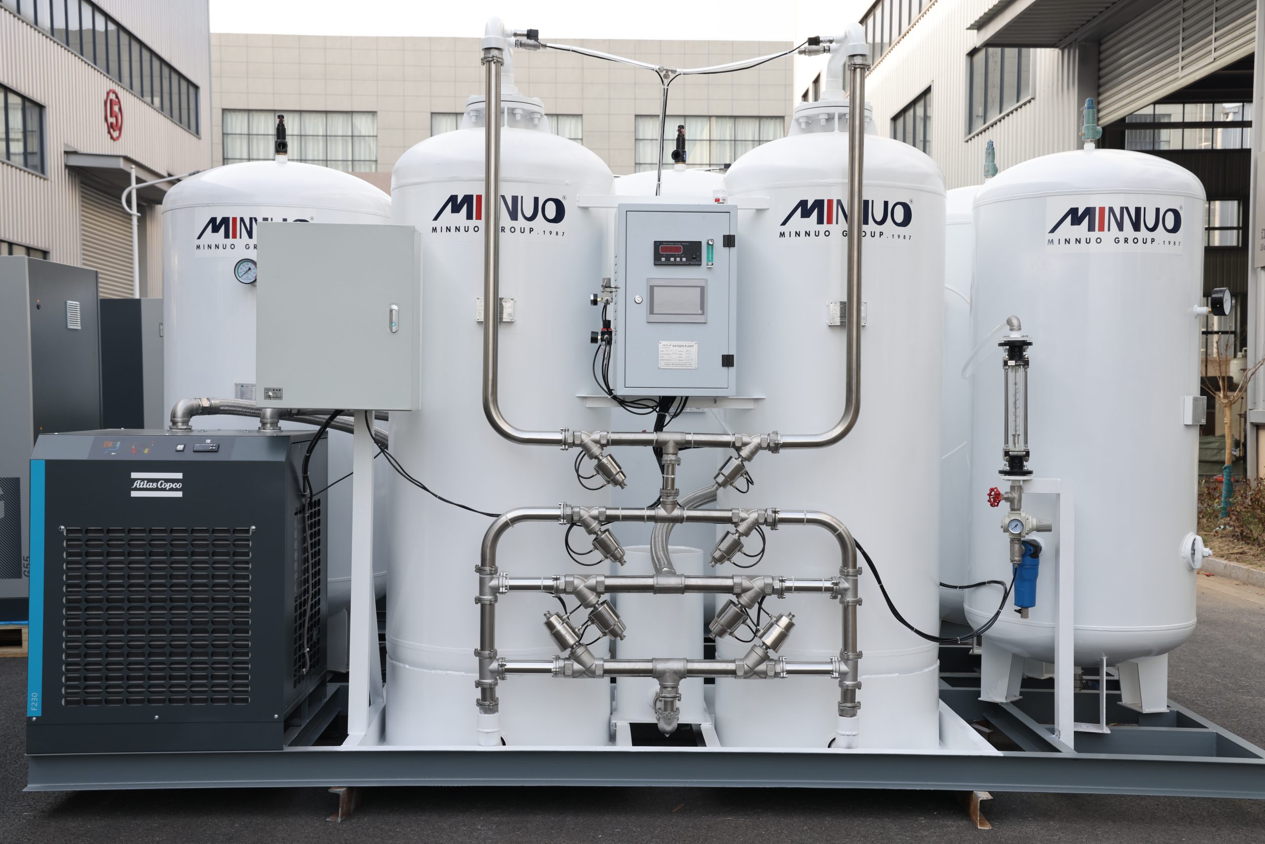
4.1 MINNUO Patented Technology Explained
4.1.1 Intelligent Filling System
MINNUO’s third-generation intelligent filling system features:
- 3D Vibration Technology: Ensures uniform compaction in all directions.
- Real-Time Density Feedback: Automatically detects every 5 cm of filling layer.
- Automatic Refill Function: Compensates for natural settling.
- Data Recording: Generates complete filling curve reports.
4.1.2 Enhanced Filtration System
Improvements compared to traditional designs:
| Parameter | Traditional Design | MINNUO Design |
| Filter Layers | Single Layer | Three-Layer Composite |
| Material | 304 Stainless Steel | 316L + PTFE |
| Service Life | 1-2 Years | 3-5 Years |
| Filtration Precision | 20 μm | 5 μm |
4.2 Preventive Maintenance System Implementation
4.2.1 Online Monitoring System Configuration
Suggested monitoring point layout:
- Air Inlet: Pressure, temperature, dew point.
- Adsorption Tower: Pressure differential, temperature, material level.
- Product Gas: Purity, flow rate, pressure.
- Exhaust End: Particle concentration monitoring.
4.2.2 Standardization of Maintenance Operations
Develop detailed SOP documents, including:
- Daily Inspections: 12 essential inspection items.
- Regular Maintenance: 28 standard operational items.
- Overhaul Specifications: 72 standard checks during disassembly.
- Spare Part Replacement: Clear standards and procedures for replacement.
Chapter 5: Economic Benefit Analysis
5.1 Cost Savings Estimation
Expected benefits after implementing the complete solution:
| Project | Before Improvement | After Improvement | Annual Savings (USD) |
| Molecular Sieve Consumption | 5%/Year | 1.5%/Year | 11,000 |
| Power Consumption | 0.5 Yuan/m³ | 0.42 Yuan/m³ | 17,000 |
| Maintenance Costs | 8,500 USD | 2,500 USD | 6,000 |
| Downtime Loss | 22,500 USD | 4,500 USD | 18,000 |
| Total | – | – | 53,000 |
5.2 Investment Return Period
Typical economic evaluation of renovation projects:
- Renovation Investment: Approximately 70,000 USD
- Annual Operating Savings: 53,000 USD
- Payback Period: Approximately 1.3 years
- Equipment Lifespan Extension: 3-5 years
Chapter 6: Technological Development Trends
6.1 New Molecular Sieve Materials
Industry R&D Directions:
- Composite Molecular Sieves: Organic-inorganic hybrid materials.
- Nano Coating Technology: Surface enhancement treatments.
- Self-Healing Materials: Automatic repair of micro-damage.
6.2 Intelligent Maintenance Systems
Future Technological Features:
- AI Fault Prediction: 30-day advance warning of potential faults.
- Digital Twin: Real-time mapping of physical equipment with virtual models.
- Blockchain Traceability: Immutable records of full lifecycle data.
Chapter 7: Conclusions and Recommendations
Through a systematic analysis of the nitrogen generator’s carbon molecular sieve leakage issue, the following conclusions can be drawn:
- Multiple Factors at Play: Leakage is the result of the combined effect of various factors, including equipment, processes, and operations.
- Preventable and Controllable: Leakage risks can be effectively controlled through systematic solutions.
- Significant Economic Benefits: The returns from professional maintenance far exceed the investment costs.
MINNUO‘s Professional Recommendations for Users:
- Establish Full Lifecycle Management: Create comprehensive records from equipment selection to decommissioning.
- Develop a Professional Team: At least two certified operators should be trained.
- Regular Professional Assessments: Invite the original manufacturer for system evaluations annually.
Chapter 8: Summary
As an industry-leading manufacturer of nitrogen generators, MINNUO offers comprehensive services ranging from equipment selection, installation, and commissioning to maintenance and support. Feel free to contact our technical expert team for customized solutions at any time.


 sales2:+86 17506119168