One of the most frequently asked questions when using a PSA nitrogen generator is: “What is the actual air consumption?” This is directly related to the selection of the air compressor, operating costs, and the overall energy efficiency of the system. This article provides a systematic explanation of how to calculate air consumption for PSA nitrogen generators, the key influencing factors, and energy-saving optimization strategies—helping you precisely control the utilization efficiency of every cubic meter of compressed air.
To calculate the air consumption of a Pressure Swing Adsorption (PSA) nitrogen generator, multiply the target nitrogen output by the air-to-nitrogen ratio corresponding to the required purity, and divide by 60, as follows: Air Consumption Q = (Nitrogen Flow × Air-to-Nitrogen Ratio) / 60. The air-to-nitrogen ratio increases with higher nitrogen purity; for example, a purity of 99.99% corresponds to a ratio of 4.1. Additionally, correction factors such as temperature, pressure, altitude, system configuration, adsorbent performance, and energy efficiency should be taken into account for dynamic adjustment and optimized setup.
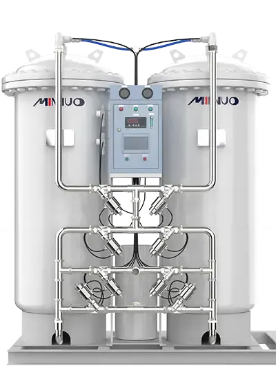
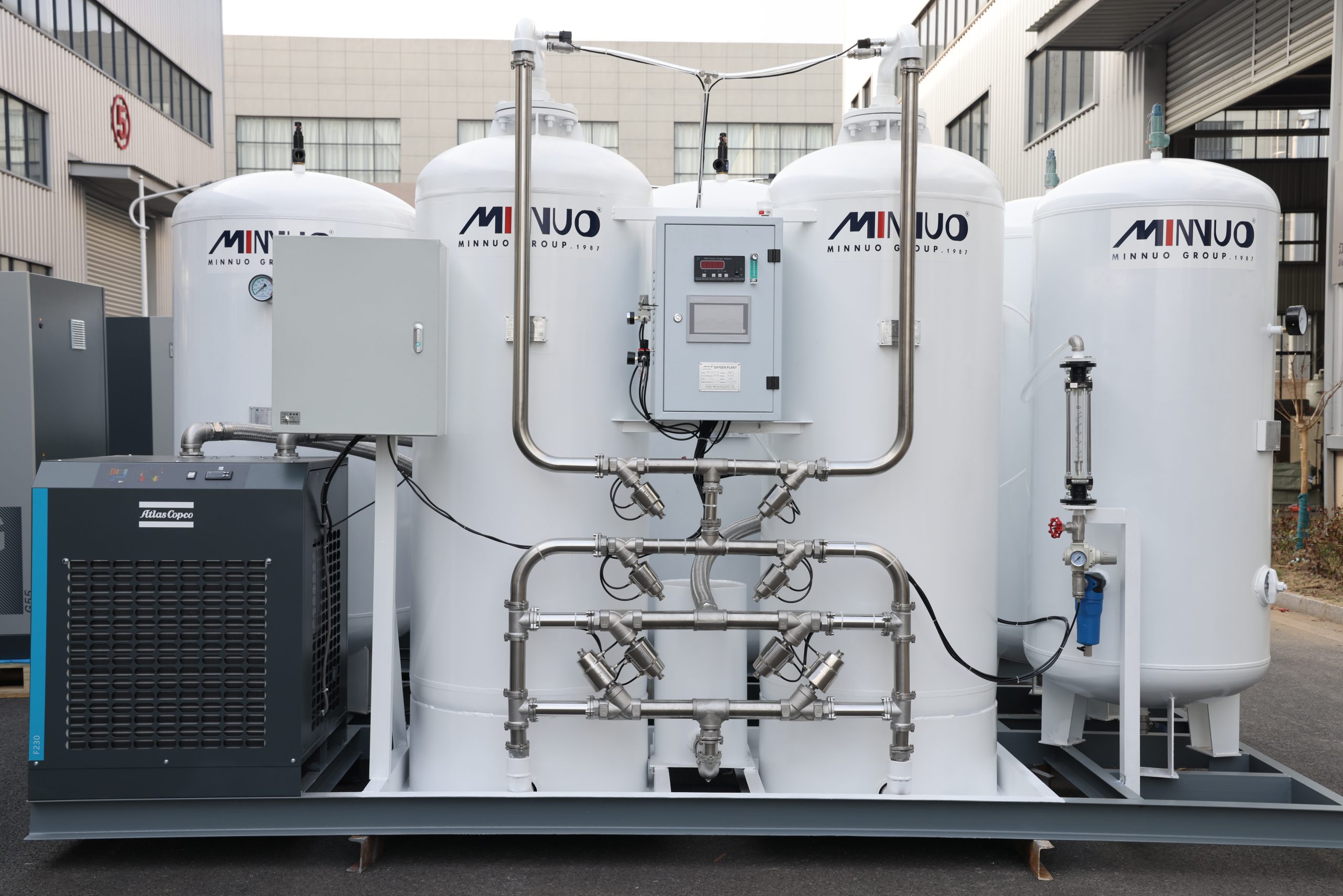
I. Core Architecture of a PSA Nitrogen Generation System
1.1 Five Coordinated Functional Units
Pressure Swing Adsorption (PSA) nitrogen generation is one of the mainstream methods for industrial nitrogen production. A complete PSA nitrogen system typically includes the following five functional units working in synergy:
- Compressed Air Purification Unit: Determines the quality of air entering the adsorption tower. The system is equipped with three purification stages: precision filters, activated carbon adsorbers, and a refrigerated dryer. This setup controls the dew point to ≤ -70°C, reduces oil content to ≤ 0.01 ppm, prevents carbon molecular sieve contamination, and extends its service life.
- Compressed Air Buffering Unit: A dual-tank parallel design effectively eliminates pressure pulsation, ensuring system pressure remains stable within ±0.02 MPa.
- Oxygen-Nitrogen Separation Unit: The core consists of dual adsorption towers filled with carbon molecular sieves. MINNUO’s sieves deliver a nitrogen recovery rate of 45%–52%, showcasing excellent performance.
- Nitrogen Buffering Unit:The output nitrogen first enters the buffer tank to ensure stable and uninterrupted gas supply, preventing purity instability caused by fluctuations at the point of use. The buffer tank volume is typically calculated based on the formula “gas production rate × buffer time” and can be determined using the formula V = Q nitrogen * t / 60, where the buffer time t is usually between 2 to 5 minutes.
- Smart Control Unit: Equipped with a Siemens PLC system for closed-loop monitoring and control of pressure, purity, and flow. Remote networking and predictive maintenance are supported.
1.2 The Critical Role of the Compressed Air System
Compressed air is the primary energy consumer in the nitrogen system, so its configuration plays a decisive role in air consumption:
Screw Air Compressor:
Variable frequency screw compressors are recommended. Compared to traditional fixed-frequency units, they can save 15%–30% energy.
Buffer Tank Design Specification:
The buffer tank volume (V) is calculated as:
V = (Q × t) / (P × η)
- Q = maximum system air consumption (m³/min)
- t = buffering time (min)
- P = working pressure (MPa)
- η = volume efficiency (typically 0.8)
Reference:
For every 10 m³/min output, a 3 m³ buffer tank is recommended.
Condensate Treatment System:
Equipped with an automatic drain valve and high-efficiency oil-water separator, capable of discharging 99.8% of liquid contaminants.
II. Air Consumption Calculation Model & Technical Parameters
2.1 Basic Formula Derivation
PSA nitrogen generator air consumption is not a single fixed value but depends on output, purity requirements, and system design. The basic formula is:
Q = (N₂ Flow × Air-to-Nitrogen Ratio) / 60
- N₂ Flow refers to the target nitrogen output (Nm³/h)
- Air-to-Nitrogen Ratio is the volume ratio of compressed air to nitrogen, closely linked to purity
- 60 is the conversion factor from hours to minutes
Typical Air-to-Nitrogen Ratios:
| Nitrogen Purity | Air-to-Nitrogen Ratio |
| 99.9% | 3.2 |
| 99.99% | 4.1 |
| 99.999% | 5.6 |
2.2 Sample Calculation
Case: Requirement of 50 Nm³/h nitrogen at 99.99% purity
Calculation:Q = (50 × 4.1) / 60 = 3.42 m³/min
A recommended compressor capacity would be 4 m³/min to allow a 10%–15% safety margin for temperature fluctuations or peak loads.
2.3 Dynamic Condition Correction Factors
- Temperature: For every 10°C increase, air consumption rises by 2.3%
- Pressure Differential: Each 0.1 MPa increase in pressure drop reduces separation efficiency by 1.8%
- Altitude: For every 300m elevation, air density drops, reducing nitrogen output by ~5%
III. Six Key Factors Affecting Air Consumption
3.1 Adsorbent Performance Metrics
High-quality carbon molecular sieves (e.g., CMS-240) offer:
- Adsorption capacity ≥ 28 ml/g
- Compressive strength ≥ 65 N/pellet
- Wear rate ≤ 0.8% per year
Better adsorbents lead to higher output and lower energy use.
3.2 Process Parameter Optimization
Adsorption Cycle Time:
Ranges from 30–120 seconds; optimizing ΔP (pressure difference) can find the “lowest energy” operating point.
Pressure Control:
- Adsorption: 0.6~0.8 MPa
- Desorption: -0.03~-0.05 MPa
Smaller pressure differentials improve energy efficiency.
3.3 Energy Efficiency Ratio Analysis
Energy efficiency ratio (E) is defined as:
E = Nitrogen Output / Power Consumption
- High-efficiency systems: ≥ 0.25 kWh/Nm³
- Standard systems: 0.35–0.45 kWh/Nm³
IV. Energy-Saving Optimization Techniques
4.1 Intelligent Control Strategy
PID Self-Tuning:
Response time < 50 ms, rapidly adapts to purity or flow changes
Predictive Maintenance:
- Pressure sensors: ±0.25% FS
- Flow meters: ≤0.5% repeatability
- Early warnings for sieve clogging or compressor anomalies
4.2 Waste Heat Recovery
Reusing 90°C exhaust from compressors:
- For workshop heating or hot water (60–80°C)
- Energy benefit: 3–5 kW heat recovery per 1 m³/min air
4.3 Modular Design Advantages
MINNUO patented modular systems:
- Capacity scalable to 300 Nm³/h via parallel expansion
- Backup modules switch online within 15 seconds
- Multi-module operation saves 12%–18% energy
V. Practical Guide for Equipment Selection
5.1 Application Scenario Matrix
| Parameter | Food Grade | Electronics Grade | Chemical Grade |
| Nitrogen Purity | 99.9% | 99.999% | 99.5% |
| Working Pressure | 0.5 MPa | 0.7 MPa | 0.6 MPa |
| Fluctuation Range | ±2% | ±0.5% | ±5% |
5.2 Air Compressor Selection Formula
P = 1.1 × Q × ln(P₂/P₁) / η
Where η is mechanical efficiency (recommended: 0.85–0.92)
5.3 Lifecycle Cost Structure
- Initial equipment investment: 35%–45%
- Power operating cost: 50%–60%
- Maintenance & consumables: 5%–10%
Proper selection and matching of working conditions is key to lowering TCO (Total Cost of Ownership).
VI. Expert Q&A
Q1: How to reduce air consumption in existing systems?
Recommended measures:
- Upgrade to high-capacity CMS molecular sieve materials
- Optimize adsorption-equalization-desorption time cycles to eliminate inefficiencies
- Add waste heat recovery for up to 15% energy savings
Q2: How to handle frequent compressor start/stop issues?
- Adjust buffer tank size to 1.2× the theoretical value
- Implement hysteresis (bandwidth) pressure control
- Add a Variable Speed Drive (VSD) for soft start and pressure stabilization
Nitrogen Generation Systems for Offshore Oil & Gas Vessels
As the demand for offshore exploration grows, the need for specialized nitrogen generator for oil and gas vessels and nitrogen generator for oil and gas ships has become critical.
At Minnuo, we understand the harsh marine environment. Our marine-grade systems feature:
- Superior Anti-corrosion: Built with stainless steel components and specialized coatings to withstand salt spray and high humidity.
- Compact & Modular Design: Optimized for the limited deck space typical of oil and gas ships.
- Maritime Certification: Our systems can be built to comply with DNV, BV, ABS, or LR standards, ensuring full compliance with international maritime safety regulations.
Why Choose Containerized Nitrogen Systems for Onsite Use?
For remote locations, oil field generators must be mobile and rugged. Minnuo’s Containerized Nitrogen Systems are the gold standard for onsite nitrogen generators for oil and gas.
- Plug-and-Play: Fully integrated within a standard ISO container for easy transport via truck or ship.
- All-Weather Protection: The reinforced housing protects sensitive components from sandstorms, rain, and extreme temperatures.
- Versatility: Ideal for rapid deployment in pipeline pigging, purging, and well-testing applications.
Technical Features: Explosion-proof, High Pressure, and High Purity
Our oilfield gas generators are engineered for the extreme:
- Explosion-proof Standards: Equipped with ATEX/IECEx certified components for Zone 1 or Zone 2 hazardous areas.
- High-Pressure Output: Capable of delivering nitrogen at pressures required for deep-well injection without the need for additional bulky boosters.
- Purity Control: Adjustable purity levels from 95% to 99.999% to meet specific operational needs.
Cost-effectiveness: Onsite Nitrogen vs. Liquid Nitrogen
Many operators are concerned about the liquid nitrogen generator price and the ongoing operational costs of bulk liquid delivery.
While the initial liquid nitrogen generator price might seem like a significant investment, the ROI of an onsite system is unmatched:
- Eliminate Logistics: No more waiting for cryogenic tankers or paying for “evaporation loss.”
- Lower Carbon Footprint: Reducing transport significantly lowers your project’s environmental impact.
- Predictable Costs: Fixed operational costs regardless of market fluctuations in liquid gas prices.
Conclusion
As a pioneer with over 30 years of experience in gas separation, MINNUO continues to drive innovation in PSA nitrogen generation technology. We recommend users prioritize dynamic air consumption indicators when selecting equipment and choose certified systems like ours with ISO8573 compliance.Visit our official website for customized solutions—our engineering team is ready to provide full lifecycle energy efficiency optimization services.


 sales2:+86 17506119168