
A chemical storage tank without proper inerting is a potential incident waiting to happen. Flammable vapors, oxygen ingress, moisture contamination—any of these can compromise product quality, create safety hazards, or violate environmental permits. A properly sized PSA nitrogen generator delivers the continuous blanketing gas needed to maintain safe tank atmospheres, but undersizing leads to inadequate protection while oversizing wastes capital and energy. This guide provides the calculation methodology to size a nitrogen generation system correctly for tank blanketing and inerting applications.
I. Why Chemical Storage Tanks Require Nitrogen Blanketing
Nitrogen blanketing replaces the vapor space above stored liquids with an inert atmosphere that prevents undesirable reactions and emissions.
1. Fire and Explosion Prevention
Flammable solvents, fuels, and chemical intermediates form explosive vapor-air mixtures when oxygen is present. Nitrogen inerting reduces oxygen concentration below the limiting oxygen concentration—typically 8-12% for most hydrocarbons—rendering the vapor space non-flammable regardless of fuel concentration.
2. Product Quality Protection
Oxygen-sensitive materials—amines, monomers, unsaturated compounds, and certain pharmaceutical intermediates—degrade through oxidation. Discoloration, viscosity changes, and peroxide formation are common consequences. Nitrogen blanketing maintains product specification throughout storage duration.
3. Moisture Exclusion
Atmospheric breathing through conservation vents introduces humid air. Water absorption by hygroscopic chemicals alters composition, promotes hydrolysis reactions, and accelerates tank corrosion. Dry nitrogen provides a moisture-free vapor space.
4. Regulatory Compliance
Environmental regulations increasingly require vapor control on storage tanks. Nitrogen blanketing combined with closed vent systems reduces volatile organic compound emissions, helping facilities meet EPA and local air quality requirements.
II. Nitrogen Demand Calculation for Tank Blanketing
Accurate PSA nitrogen generator sizing begins with quantifying nitrogen consumption under normal operation and worst-case scenarios.
1. Liquid Movement Compensation (API 2000 Methodology)
When liquid is pumped out of a tank, nitrogen must flow in to prevent vacuum and maintain inert atmosphere. When liquid fills the tank, vapor space compresses and nitrogen may vent. The required nitrogen flow rate equals the maximum liquid withdrawal rate.
Basic Calculation:
Nitrogen Flow (SCFH) = Maximum Pump-Out Rate (GPM) × 8.02
Example: A 200 GPM transfer pump requires 200 × 8.02 = 1,604 SCFH (approximately 45 Nm³/hr) nitrogen inflow to prevent vacuum.
2. Thermal Breathing Compensation
Ambient temperature changes cause vapor space expansion and contraction. Cooling contracts the vapor space, drawing in nitrogen. Heating expands vapor, venting nitrogen. API 2000 provides thermal breathing requirements based on tank capacity.
| Tank Capacity (gallons) | Thermal Breathing Requirement (SCFH N₂) |
| 10,000 | 600 |
| 20,000 | 1,000 |
| 50,000 | 1,800 |
| 100,000 | 3,000 |
For insulated tanks or underground storage, thermal breathing requirements reduce significantly—consult API 2000 Appendix A for specific reduction factors.
3. Continuous Purge Requirements
Some processes require continuous nitrogen sweep to remove evolved gases or maintain extremely low oxygen concentrations. Purge rate depends on vessel volume and desired oxygen reduction curve.
Dilution Purging Formula:
Q = (V / t) × ln(C₁ / C₂)
Where:
- Q = Purge nitrogen flow rate (volume/time)
- V = Vessel vapor volume
- t = Time allowed for purging
- C₁ = Initial oxygen concentration (typically 21%)
- C₂ = Target oxygen concentration
4. Leakage and Valve Bleed Compensation
Valve packing, flange connections, and sample points continuously lose small nitrogen volumes. Add 5-10% to calculated demand for typical installations. Older facilities with known leakage issues may require higher margins.
5. Total Nitrogen Demand Summary
Total N₂ Flow = Liquid Movement + Thermal Breathing + Continuous Purge + Leakage Margin
Choose the highest coincident demand rather than summing all possible flows if events do not occur simultaneously. For example, maximum pump-out typically does not coincide with maximum cooling rate.
III. Worked Example: Methanol Storage Tank
A 50,000-gallon methanol tank illustrates the calculation process.
Tank Parameters:
- Capacity: 50,000 gallons
- Maximum pump-out rate: 300 GPM
- Location: Uninsulated aboveground tank, temperate climate
- Target oxygen concentration: <8%
Step 1: Liquid Movement
300 GPM × 8.02 = 2,406 SCFH (68 Nm³/hr)
Step 2: Thermal Breathing
From API 2000 table: 1,800 SCFH (51 Nm³/hr)
Step 3: Continuous Purge
Not required for this application (methanol stable under nitrogen)
Step 4: Leakage Margin
10% of highest demand = 240 SCFH
Step 5: Peak Demand Determination
Liquid movement (2,406 SCFH) and thermal breathing (1,800 SCFH) do not occur simultaneously. Design for 2,646 SCFH (liquid movement + leakage margin).
Step 6: Safety Factor
Add 15-20% for future expansion and unexpected conditions: 2,646 × 1.2 = 3,175 SCFH (90 Nm³/hr)
Result: Specify a PSA nitrogen generator rated for 90 Nm³/hr minimum.
IV. Nitrogen Purity Requirements for Blanketing
Purity selection impacts both PSA system cost and blanketing effectiveness.
1. Standard Blanketing: 95-97% Purity
For most flammable liquid storage, 95-97% nitrogen provides adequate oxygen displacement. The 3-5% oxygen content in the nitrogen stream, when diluted into the tank vapor space, results in oxygen concentrations well below limiting oxygen concentrations for common hydrocarbons.
2. Reactive Chemical Storage: 98-99.9% Purity
Monomers (styrene, vinyl acetate, acrylic acid), pyrophoric materials, and certain pharmaceutical intermediates demand higher purity nitrogen. Oxygen levels below 0.5% may be required to prevent polymerization or degradation. Specify 99%+ purity for these applications.
3. Moisture Specification
Dew point is equally important. Water vapor in nitrogen accumulates in tanks storing hygroscopic materials or operating in cold climates where condensation occurs. Specify -40°F pressure dew point for general service and -70°F for critical moisture-sensitive applications.
4. Economic Balance
Higher purity nitrogen increases PSA system capital cost and energy consumption. Balance purity against actual process requirements. Many chemical plants standardize on 97-99% nitrogen plant-wide, using local purification only for exceptional applications.
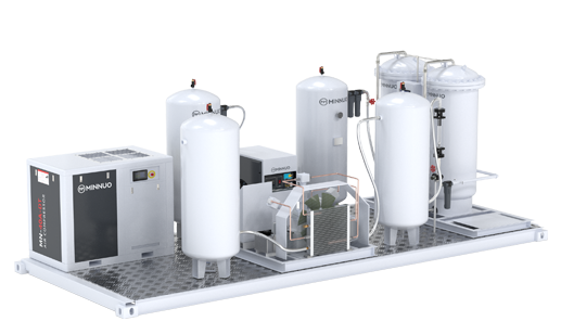
V. PSA Nitrogen Generator Sizing and Configuration
With nitrogen demand and purity defined, select the appropriate PSA system configuration.
1. Capacity Sizing
Size the PSA generator for peak continuous demand plus safety margin. Do not size for average demand—blanketing demand varies widely based on operating schedule and weather conditions.
2. Buffer Tank Sizing
A nitrogen receiver tank smooths demand fluctuations and provides reserve during generator maintenance. Size buffer capacity for 15-30 minutes of peak consumption. For the 90 Nm³/hr example above, a 30-45 Nm³ receiver volume (approximately 1,000-1,500 gallon equivalent) is appropriate.
3. Redundancy Considerations
Critical blanketing applications protecting high-value inventory or safety-critical systems justify redundancy:
- N+1 configuration: One spare generator module
- Liquid nitrogen backup: Automatically activated if PSA purity or pressure drops
- Dual feed capability: Manual connection for temporary nitrogen supply
4. Control System Integration
Modern PSA nitrogen systems for blanketing include:
- Oxygen analyzer with alarm and venting: Diverts off-spec nitrogen to atmosphere
- Pressure control: Maintains consistent header pressure for blanketing valves
- Remote monitoring: Cellular or Ethernet connectivity for off-site oversight
- Automatic start/stop: Matches production to demand, reducing energy consumption
5. Altitude and Ambient Temperature Effects
PSA generators lose capacity at elevation—derate approximately 1% per 100 meters above sea level. High ambient temperatures reduce air compressor efficiency and may require oversizing. Confirm the generator rating applies at site conditions, not sea level standard conditions.
VI. System Integration with Tank Blanketing Valves
The PSA nitrogen generator supplies gas to a header serving multiple tanks. Proper integration ensures reliable blanketing.
1. Blanketing Valve Selection
Tank blanketing valves modulate nitrogen flow to maintain slight positive pressure—typically 0.5 to 2 inches water column. Select valves sized for maximum pump-out flow at available nitrogen header pressure.
2. Conservation Vent Coordination
The conservation vent (pressure-vacuum relief valve) must be set slightly above the blanketing valve setpoint to prevent unnecessary nitrogen venting. Typical settings: blanketing valve at 1.0 inch WC, conservation vent at 2.0 inches WC.
3. Oxygen Monitoring at Tank Outlet
For critical applications, install oxygen analyzers sampling from the tank vent line. This confirms blanketing effectiveness and provides early warning of nitrogen system or blanketing valve malfunction.
Frequently Asked Questions
Q1: Can one PSA nitrogen generator supply multiple storage tanks?
A1: Yes, this is standard practice. Size the generator for the simultaneous peak demand of all connected tanks. Consider operating schedules—tanks filled and emptied on different shifts create lower coincident demand than multiple tanks discharging simultaneously.
Q2: What nitrogen purity is required for API 2000 compliance?
A2: API 2000 addresses tank venting requirements for pressure and vacuum protection but does not specify nitrogen purity. Purity requirements derive from process safety (NFPA 69) and product quality considerations. For most flammable liquid storage, 95-97% nitrogen provides adequate inerting.
Q3: How does nitrogen blanketing differ from nitrogen inerting?
A3: Blanketing maintains an inert atmosphere during normal storage, compensating for liquid movement and thermal breathing. Inerting is the initial purge to reduce oxygen concentration from atmospheric to safe levels. Inerting requires higher nitrogen flow for a limited duration; blanketing requires lower continuous flow.
Q4: Should I include a backup nitrogen supply for blanketing?
A4: For tanks containing materials with high safety or economic consequences of atmosphere loss, yes. Liquid nitrogen backup or a standby PSA module provides protection during generator maintenance or unexpected outage. Evaluate the cost of backup against potential product loss or safety incident cost.
Q5: What pressure is required for tank blanketing nitrogen?
A5: Tank blanketing valves typically require 15-30 PSIG inlet pressure. PSA nitrogen generators produce nitrogen at 60-100 PSIG standard, requiring pressure reduction before the blanketing valve. Include a pressure regulator with downstream relief in the nitrogen header design.
Q6: How do I calculate nitrogen consumption for pressure-cycle blanketing?
A6: Some tanks use pressure-cycle blanketing where nitrogen flows only when tank pressure drops below setpoint. Calculate consumption by multiplying tank volume by pressure cycles per day. For a 10,000-gallon tank cycling between 0.5 and 1.5 inches WC, nitrogen usage per cycle is approximately 50-100 SCF. Multiply by cycles per day for daily consumption.
Conclusion
Proper PSA nitrogen generator sizing for tank blanketing and inerting applications requires systematic calculation of liquid movement, thermal breathing, purge requirements, and system losses. The API 2000 methodology provides a defensible basis for these calculations, while safety factors and site condition adjustments ensure the installed system meets actual operating demands. A correctly sized PSA nitrogen system delivers reliable inerting protection without excessive capital or operating cost.
At MINNUO, we engineer PSA nitrogen generation systems configured specifically for chemical plant blanketing and inerting applications. Our systems comply with API 2000 and NFPA 69 guidelines and include integrated oxygen analysis, automatic pressure control, and remote monitoring capability. Every MINNUO nitrogen generator includes warranty coverage and access to our engineering team for commissioning support, operational troubleshooting, and on-site field service when required. Whether protecting a single storage tank or an entire tank farm, MINNUO delivers reliable on-site nitrogen supply.

 sales2:+86 17506119168