In the field of industrial nitrogen production, membrane nitrogen generators are widely used due to their simple structure, convenient operation, and low energy consumption. However, if the equipment operates at high temperatures, it may cause irreversible damage to core components (such as the membrane module) and even affect nitrogen production efficiency. Based on the working principle of membrane nitrogen generators and the characteristics of their temperature control systems, this article analyzes the causes of high temperatures and proposes targeted solutions.
Having extreme temperature alarms or C1557 overheat warnings on your membrane nitrogen generator or air compressor?This guide explains typical overheating causes, how they affect your N2 membrane module, what C1557 overheat preventive control means, and step‑by‑step checks you can do before calling service.
The main causes of high temperatures in membrane nitrogen generators include excessively high ambient temperature, abnormal airflow system, temperature control system malfunction, abnormal heater power, and aging or contamination of the membrane module. These factors can lead to poor heat dissipation or excessive heat generation, affecting nitrogen production efficiency. To address these issues, measures such as improving ventilation, cleaning pipeline filters, regularly inspecting temperature control components, optimizing heater power configuration, and maintaining the membrane module can be taken to ensure stable operation and extend the equipment’s service life.
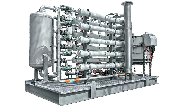
Extreme Temperature in Air Generators
In many plants, membrane nitrogen generators are installed together with air compressors or complete air generator skids, so extreme temperature problems usually appear at the system level rather than on a single unit. When the air generator runs with high discharge temperature for a long time, the hot compressed air will enter the membrane skid and significantly increase the inlet temperature of the nitrogen membrane module.
Typical extreme temperature scenarios in air generators include insufficient cooling of the compressor, cooling fan failure, fouled after‑coolers, or operation in very hot climates without adequate ventilation. In these cases, the compressor discharge temperature and pipeline surface temperature are obviously higher than normal, and operators may also observe more frequent high‑temperature alarms or overheat trips on both the air generator and the membrane nitrogen generator.
To control extreme temperature in air generators, the first step is to check the cooling system, including cooling water flow, cooling water temperature, air‑cooled fan direction and speed, as well as cleanliness of the heat exchangers. At the same time, improving the installation environment with better ventilation, sun shading, and separation from other heat sources will help reduce the overall ambient temperature and protect both the air generator and the downstream N2 membrane system.
How Overheating Damages the Nitrogen Membrane Module (N2 Membrane)
The nitrogen membrane module is a polymer‑based separation element that is very sensitive to long‑term exposure to high temperature. When the N2 membrane operates above the recommended temperature range, the polymer chains gradually degrade, leading to irreversible changes in permeability and selectivity between nitrogen and oxygen.
Overheating accelerates membrane aging, causing a continuous increase in gas flow resistance through the hollow fibers and a gradual drop in nitrogen purity at the outlet. To maintain the same nitrogen flow and purity, the system has to run at higher pressure or with longer operating hours, which increases power consumption and further raises the internal temperature of the skid.
In addition, high temperature can intensify contamination problems inside the nitrogen membrane module, such as oil vapor condensation, softening of deposited particles, and faster growth of microorganisms in humid conditions. These combined effects not only shorten the service life of the N2 membrane but can also lead to sudden performance failure, forcing unplanned shutdown and replacement of the membrane module.
I. Principles of the Temperature Control System in Membrane Nitrogen Generators
The core working mechanism of membrane nitrogen generators involves the selective permeation of oxygen and nitrogen from compressed air using hollow fiber membranes, thereby achieving efficient nitrogen separation. In this process, precise temperature control is crucial for ensuring the stability of membrane performance and the efficient operation of the entire separation process. The temperature control system mainly consists of the following key components working in coordination:
(1) Thermocouples and PID Temperature Controllers
Thermocouples, as critical components for temperature detection, can sense real-time temperature changes inside the equipment and convert temperature signals into electrical signals. The PID temperature controller receives signals from the thermocouple and processes and analyzes the temperature signals using advanced proportional (P), integral (I), and derivative (D) algorithms. Then, based on the deviation between the preset temperature value and the actual measured value, the PID controller precisely controls the on/off state of the solid-state relay (SSR) to adjust the heater’s power. This closed-loop control method allows for rapid and accurate temperature regulation, ensuring that the internal temperature remains within the set range and that the membrane separation process operates under suitable temperature conditions.
(2) Overheat Protection Device
To prevent abnormal high temperatures during operation, membrane nitrogen generators are equipped with an overheat protection device. When the internal temperature rises to ≥50°C, the overheat protection device will automatically cut off the power, stopping the heater to avoid damage caused by excessive temperature. When the temperature drops to ≤35°C, the overheat protection device will automatically restore power, allowing the heater to resume operation and maintain the equipment’s normal operating temperature. This overheat protection mechanism provides a reliable safety layer, effectively preventing temperature runaway caused by temperature control system malfunctions or other reasons.
(3) Pressure Interlock Protection
The pressure interlock protection mechanism is another important component of the temperature control system in membrane nitrogen generators. When the air pressure reaches ≥0.4MPa, the pressure switch will automatically close, and the heater will start working. This design aims to prevent the heater from dry firing without airflow, which could lead to equipment overheating or damage. The heater only operates when there is sufficient airflow, ensuring the safety and stability of the equipment.
II. Common Causes of High Temperature
(1) Excessively High Ambient Temperature
Poor ventilation in the installation environment or proximity to heat sources:
If the membrane nitrogen generator is installed in a poorly ventilated confined space or near high-temperature heat sources such as boiler rooms or high-temperature furnaces, the heat emitted by the equipment cannot be effectively discharged into the surrounding environment, leading to a sharp decline in heat dissipation efficiency. The internal heat continuously accumulates, eventually causing the equipment’s surface temperature to rise continuously. This situation is particularly common during high-temperature periods in summer, as the ambient temperature is already high, and poor ventilation and heat sources further exacerbate the equipment’s heat dissipation challenges.
Symptoms:
The equipment’s surface temperature noticeably increases, and touching it may feel scalding. Additionally, the equipment’s operating noise may increase due to the expansion or deformation of internal components caused by high temperatures, leading to increased mechanical friction. Furthermore, the equipment’s operational stability may be affected, potentially causing fluctuations in nitrogen purity.
(2) Abnormal Airflow System
Insufficient air supply from the compressor or pipeline blockage (e.g., filter carbon buildup):
The air compressor is a key component that provides compressed air for the membrane nitrogen generator. If the air compressor malfunctions due to piston wear, seal aging, etc., leading to insufficient air supply pressure, the airflow required for the membrane separation process cannot be met, resulting in poor airflow circulation. Additionally, if the filters in the pipeline are not cleaned or replaced for a long time, accumulating dust, oil, and carbon deposits, the pipeline may become blocked, hindering normal airflow. As a result, the heat generated inside the equipment cannot be effectively carried away by the airflow, leading to heat accumulation and high-temperature issues.
Symptoms:
Significant air pressure fluctuations can be observed on the pressure gauge, with unstable pressure readings. The heater may frequently start and stop because, when the air pressure is insufficient, the heater attempts to compensate for the heat loss. However, due to poor airflow, the heat cannot be effectively dissipated, causing the temperature to rise quickly and leading to frequent heater cycling. Additionally, the equipment’s nitrogen output may decrease, and nitrogen purity may be affected.
(3) Temperature Control System Malfunction
Thermocouple aging or signal transmission abnormalities:
Thermocouples working in high-temperature environments for extended periods may experience oxidation or corrosion of internal metal wires, leading to aging and reduced measurement accuracy. Additionally, if the signal transmission line between the thermocouple and the PID temperature controller is damaged or has poor contact, signal transmission abnormalities may occur, causing the PID controller to receive inaccurate temperature signals.
PID parameter misalignment:
The parameter settings of the PID temperature controller are crucial for temperature control accuracy and stability. If the PID parameters are set unreasonably during equipment debugging or if external interference causes parameter changes during operation, the controller’s effectiveness may decline. For example, an excessively large proportional band may cause the controller to respond slowly to temperature changes; an excessively long integral time may slow down the system’s adjustment speed, preventing timely elimination of temperature deviations; and improper differential time settings may cause system oscillations and significant temperature fluctuations.
SSR relay sticking or failure:
The solid-state relay (SSR) in the temperature control system controls the power supply to the heater. If the SSR relay operates frequently over a long period or is affected by overvoltage or overcurrent, its internal contacts may stick, preventing the relay from disconnecting normally. As a result, the heater continues to operate, causing the equipment temperature to rise continuously.
Symptoms:
The temperature controller’s displayed value deviates significantly from the actual temperature, potentially showing values much higher or lower than the actual temperature. The heater may operate uncontrollably, continuing to work even when the internal temperature exceeds the set upper limit. Additionally, the equipment’s temperature fluctuations may become unusually severe, failing to stabilize within the set temperature range.
(4) Abnormal Heater Power
Local short circuits in heating elements or excessively high power configuration:
Heating elements may experience local short circuits due to insulation damage during long-term use. When a local short circuit occurs, the resistance in the short-circuited area decreases, and the current increases, causing a sharp rise in heat generation in that area. Additionally, if the heater’s power configuration is excessively high during equipment selection or installation, exceeding the heat dissipation system’s capacity, the equipment may generate excessive heat during operation, leading to high-temperature issues.
Symptoms:
The equipment’s internal temperature rises rapidly in a short period, with the temperature increase speed significantly exceeding normal conditions. The overheat protection device may frequently trigger to prevent equipment damage due to excessive temperature. Additionally, a burning smell may be detected, caused by the decomposition of insulation materials due to local short circuits in the heating elements.
(5) Membrane Module Aging or Contamination
Membrane Module Aging Due to Polymer Material Degradation
During prolonged operation, the membrane module of a nitrogen generator is subjected to impurities, moisture, and oil contamination from compressed air, as well as factors such as temperature and pressure. These influences gradually degrade the membrane’s performance. A key manifestation of membrane aging is the decline in permeability. When permeability decreases, the resistance to gas flow through the membrane increases. As a result, more energy is required to maintain the same nitrogen output, increasing the system load and generating additional heat.
Membrane Module Contamination
Dust, oil contamination, microorganisms, and other impurities in compressed air gradually accumulate on the surface and inside the membrane module, forming deposits, a phenomenon known as membrane contamination. This contamination further reduces the membrane’s separation efficiency, making the gas separation process more challenging. Consequently, more energy is required to sustain operation, leading to increased equipment temperature. When the oil content in compressed air exceeds 0.01 ppm and particulate matter exceeds 1μm, suspended contaminants can affect the membrane module performance through the following mechanisms:
- Physical Blockage: Particulate matter forms a filter cake layer on the membrane surface, hindering gas permeability.
- Chemical Adsorption: Hydrocarbons in oil mist cause swelling reactions with the membrane material.
- Biological Growth: When humidity exceeds 60%, microorganisms proliferate inside the membrane, leading to biofouling.
Manifestations
- Decline in nitrogen purity, failing to meet production process requirements.
- Increased operational noise, caused by greater resistance to gas flow through the deteriorated membrane module, leading to internal airflow turbulence.
- Significant rise in energy consumption, as the electricity required to produce a unit volume of nitrogen increases.
| Fault Type | Typical Symptoms | Direct Consequences |
| Membrane Module Aging | Nitrogen purity decreases by ≥5%, energy consumption increases by 20%–30% | Production process fails to meet standards, increased costs |
| Temperature Control System Failure | Temperature fluctuation > ±5°C, heater continuously operates | Thermal damage to the membrane module, lifespan reduced by 50% |
III. Solutions for High Temperature Issues
(1) Optimize Equipment Operating Environment
Ensure the equipment is installed in a well-ventilated area away from heat sources:
When selecting an installation location, choose a well-ventilated, open space, avoiding confined or enclosed rooms. Additionally, ensure that there are no heat sources within at least 1 meter of the equipment, such as high-temperature furnaces or steam pipelines. If proximity to heat sources is unavoidable, implement effective insulation measures, such as installing insulation barriers.
Install cooling fans or air conditioning if necessary:
For locations with high ambient temperatures and limited ventilation, consider installing cooling fans or air conditioning to reduce the surrounding temperature. Cooling fans can be installed near the equipment’s heat dissipation outlets to accelerate heat dissipation through forced convection. Air conditioning can control the temperature of the entire equipment installation area, creating a suitable environment for stable operation.
Regularly clean dust from the equipment’s surface and heat dissipation outlets:
Dust on the equipment’s surface and heat dissipation outlets can hinder heat dissipation, so regular cleaning is necessary. Use a clean cloth to wipe the equipment’s surface, and use compressed air to blow dust from the heat dissipation outlets. It is recommended to clean the equipment’s surface at least once a week and perform a deep cleaning of the heat dissipation outlets at least once a month.
(2) Inspect the Airflow System
Check Whether the Compressor Output Pressure is Stable (Recommended: 0.7–1.0 MPa)
Regularly use a pressure gauge to monitor the compressor’s output pressure, ensuring it remains within the recommended range of 0.7–1.0 MPa. According to GB/T 38624-2020 General Technical Specification for Gas Separation Equipment, the compressor output pressure should be maintained between 0.7 and 1.0 MPa. If the pressure drops below 0.6 MPa, the low-pressure alarm system should be triggered.
If the compressor output pressure is insufficient, an inspection and maintenance should be carried out promptly. Possible causes include clogged intake filters, piston wear, and aging seals. Appropriate actions such as cleaning or replacement should be performed based on the specific issue.
Clean or replace clogged filters:
Regularly inspect and maintain the filters in the pipeline. If significant carbon buildup or clogging is found, clean or replace the filters promptly. Use specialized cleaning agents to soak and rinse the filters, then dry them with compressed air. If the filters are damaged or cannot be restored through cleaning, replace them with new ones. It is recommended to inspect the filters every three months and decide whether cleaning or replacement is needed based on the actual condition.
Check for air leaks at pipeline connections:
Carefully inspect all connections in the pipeline system for air leaks. Apply soapy water to the connections and observe if bubbles form to determine if there is a leak. If a leak is found, repair it promptly. For loose connections, tighten the nuts; for damaged seals, replace them with new ones.
Ensure the pressure switch (0.4MPa threshold) is sensitive and effective:
Regularly test the pressure switch to ensure it can close normally when the pressure reaches 0.4MPa and open when the pressure drops below 0.4MPa. Simulate pressure changes to test the pressure switch’s performance. If the pressure switch malfunctions, replace it promptly to ensure the normal operation of the pressure interlock protection mechanism.
(3) Calibrate the Temperature Control System
Regularly calibrate the thermocouple using a standard thermometer:
Calibrate the thermocouple periodically (recommended every six months) using a calibrated standard thermometer. Place the standard thermometer and the thermocouple at the same location to measure the same temperature point inside the equipment, then compare their readings. If the thermocouple’s measurement deviates beyond the allowable range, it should be adjusted or replaced promptly.
Every quarter, use a Class A thermocouple calibrator (e.g., Fluke 1551A) to perform a three-point calibration at typical operating temperatures (20°C, 35°C, 50°C). If the deviation exceeds ±1.5%, the sensor must be replaced.
Adjust PID parameters (proportional band, integral time, derivative time):
Optimize the PID temperature controller’s parameters based on the equipment’s actual operation and temperature control requirements. Use a trial-and-error method to adjust the proportional band first, observe the temperature control effect, then adjust the integral and derivative times until the best temperature control accuracy and stability are achieved. Record each adjustment’s parameter values and corresponding temperature control effects for future reference.
Test the SSR relay’s on/off function:
Regularly test the SSR relay’s on/off function. Use a multimeter to measure the relay’s contact resistance; when the relay is off, the contact resistance should be infinite; when the relay is on, the contact resistance should be close to zero. If the relay’s on/off function is abnormal (e.g., contacts sticking, failure to close or open), replace the SSR relay promptly.
(4) Adjust the Heater’s Operating Mode
Check if the heater’s rated power matches the equipment:
Carefully verify if the heater’s rated power matches the membrane nitrogen generator’s design requirements. If the heater’s power is excessively high, replace it with a heater of appropriate power. When replacing the heater, choose a reliable product that meets the equipment’s requirements and ensure proper installation.
Implement staged heating:
Use a PLC program to set a staged heating strategy. For example, during equipment startup, use lower power to preheat the equipment, allowing the internal temperature to rise slowly. When the temperature reaches a certain level, gradually increase the heater’s power to quickly reach the set temperature. This staged heating approach can effectively reduce instantaneous heat load, preventing high-temperature issues caused by sudden excessive heat generation.
(5) Maintain or Replace the Membrane Module
Test the membrane module’s permeability every six months:
Regularly test the membrane module’s permeability. Measure the oxygen and nitrogen permeation rates under specific pressure and temperature conditions to evaluate the membrane module’s performance. If a significant decline in permeability is observed, take appropriate measures promptly.
Use specialized cleaning agents to remove contaminants:
Use specialized cleaning agents to clean contaminants on the membrane module’s surface and inside. Follow the cleaning agent’s instructions carefully, controlling the cleaning temperature, time, and concentration. After cleaning, rinse the membrane module thoroughly with clean water to ensure no cleaning agent residue remains.
Replace the membrane module if it is severely aged (e.g., separation efficiency decreases by more than 30%):
If the membrane module is severely aged, with separation efficiency decreasing by more than 30%, even after cleaning and maintenance, it may not restore normal performance. In this case, replace the membrane module promptly. When replacing, choose a membrane module that matches the original equipment model and follow the correct installation steps to ensure secure and sealed installation.

IV. Preventive Maintenance Recommendations
(1) Daily Inspections
Record the operating temperature curve:
During equipment operation, record the equipment’s operating temperature daily and plot the temperature curve. By observing the temperature curve’s trend, abnormal temperature fluctuations can be detected promptly. For example, if the temperature curve shows a continuous upward trend or sudden significant fluctuations, it may indicate potential issues requiring further investigation.
Investigate immediately if abnormal fluctuations are detected:
If abnormal temperature fluctuations are detected, stop the equipment immediately and conduct a comprehensive inspection. Check the equipment’s operating environment, airflow system, temperature control system, heater, and membrane module to identify the cause of the abnormal fluctuations and take appropriate corrective measures.
(2) Quarterly Maintenance
Clean electrical contacts:
Clean the equipment’s electrical contacts quarterly. Electrical contacts may oxidize or accumulate dust during long-term use, increasing contact resistance and affecting normal operation. Use alcohol swabs to clean the electrical contacts, removing oxides and dust to ensure good contact.
Check the sensitivity of the overheat protection switch:
Test the overheat protection switch’s sensitivity. Simulate a temperature rise in the equipment and observe if the overheat protection switch cuts off power promptly at the set temperature (≥50°C). Also, check if the switch restores power normally when the temperature drops to the set value (≤35°C). If the overheat protection switch’s sensitivity is abnormal, adjust or replace it promptly.
(3) Annual Overhaul
Comprehensively test the temperature control system:
Conduct a comprehensive test of the membrane nitrogen generator’s temperature control system annually. Test the performance of the thermocouple, PID temperature controller, SSR relay, and overheat protection device. Through comprehensive testing, identify potential issues in the temperature control system and repair or replace relevant components to ensure the system’s reliability and stability.
Update PLC program logic:
As the equipment operates over time and production processes change, the original PLC program logic may no longer fully meet the equipment’s operational needs. Therefore, optimize and update the PLC program annually, adjusting the program logic based on the equipment’s actual operation and new control requirements to improve automation control levels and operational efficiency.
Optimize the heating control algorithm:
Optimize the heating control algorithm, adjusting the heating control strategy based on the equipment’s operational data and actual control effects to further improve temperature control accuracy and stability, reducing the risk of high-temperature issues caused by improper heating control.
FAQ: C1557 Overheat Preventive Control / Current Limit
Q: What does the C1557 overheat preventive control / current limit alarm mean?
A: C1557 overheat preventive control or current limit is typically an alarm or protective function in the drive or control system, indicating that the device has detected a temperature or current value close to its safe limit and is taking action to protect itself.
Q: What happens to the system when C1557 is active?
A: When this alarm is active, the controller may automatically reduce output current, limit motor speed, or stop the heater to prevent further temperature rise. In some configurations, it can also trigger a controlled shutdown to avoid damage to the power electronics, motor, or compressor.
Q: What are the common causes of a C1557 overheat preventive control alarm?
A: Typical causes include poor ventilation in the electrical cabinet, cooling fan failure, dust‑blocked cooling channels or heat sinks, excessive ambient temperature around the panel, long‑term operation at maximum load, or mechanical overload of the compressor or blower.
Q: What basic checks should be performed when C1557 appears?
A: Operators should first clean the control cabinet and drive cooling channels, verify that all fans are running in the correct direction and at the rated speed, and measure the ambient temperature around the cabinet. It is also important to check whether the compressor or blower is running within its rated pressure and flow range and to confirm that supply voltage is stable.
Q: When should the equipment supplier or drive manufacturer be contacted?
A: If the C1557 overheat preventive control alarm appears repeatedly after cleaning and basic ventilation checks, or if current and temperature remain high under normal load, operating data (current, temperature, pressure, running hours) should be recorded and sent to the equipment or drive supplier. They can then analyze the trend, review drive parameters, and recommend further diagnostics or parameter optimization to prevent future overheat events.
V. Conclusion
High-temperature issues in membrane nitrogen generators are often caused by poor heat dissipation, control failures, or component aging. By accurately identifying the source of the problem and combining environmental optimization, system calibration, and regular maintenance, membrane module damage can be effectively avoided, ensuring long-term stable operation of the equipment. In practice, it is recommended to maintain equipment operation logs and implement predictive maintenance using intelligent monitoring systems to further enhance nitrogen production efficiency and safety.
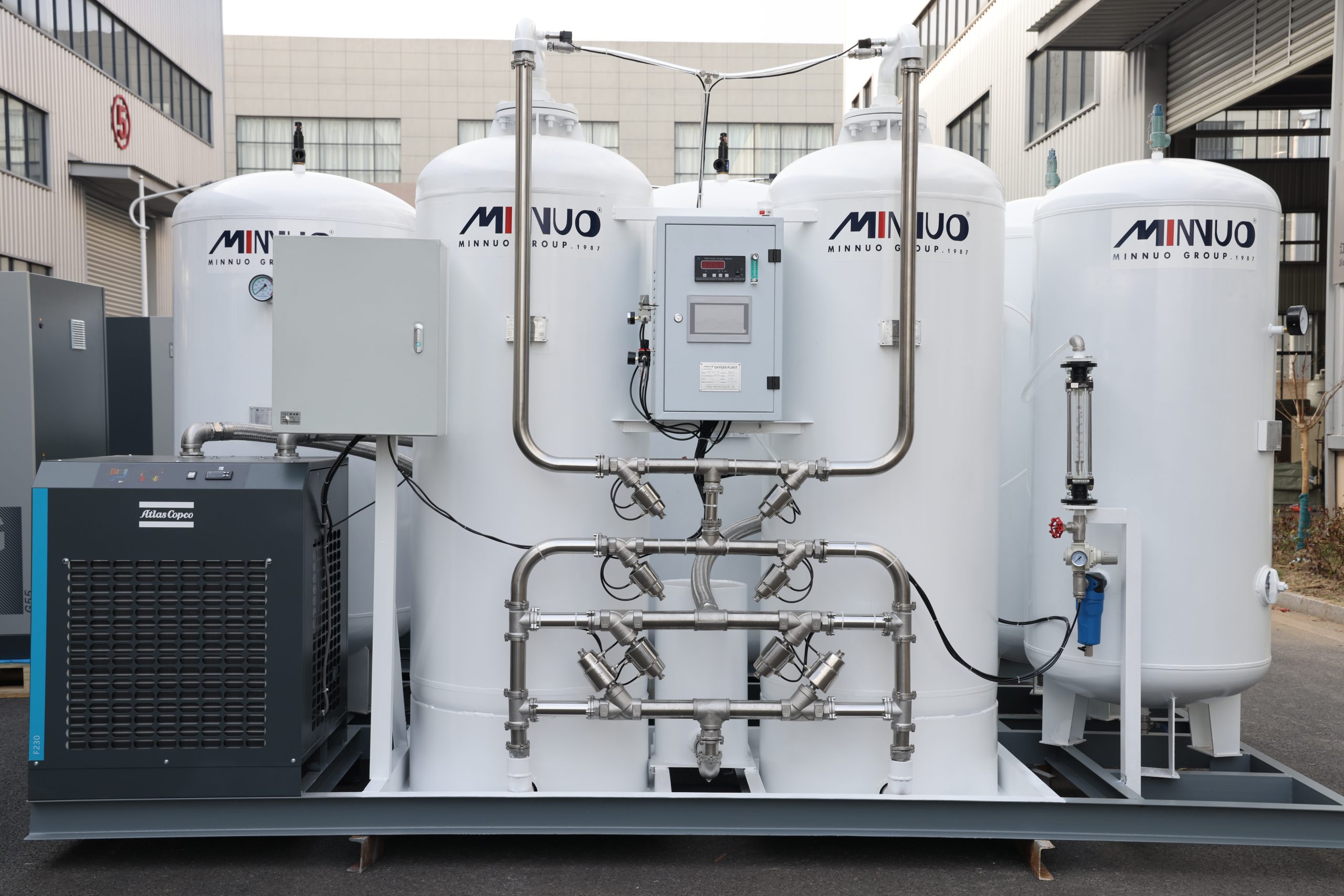
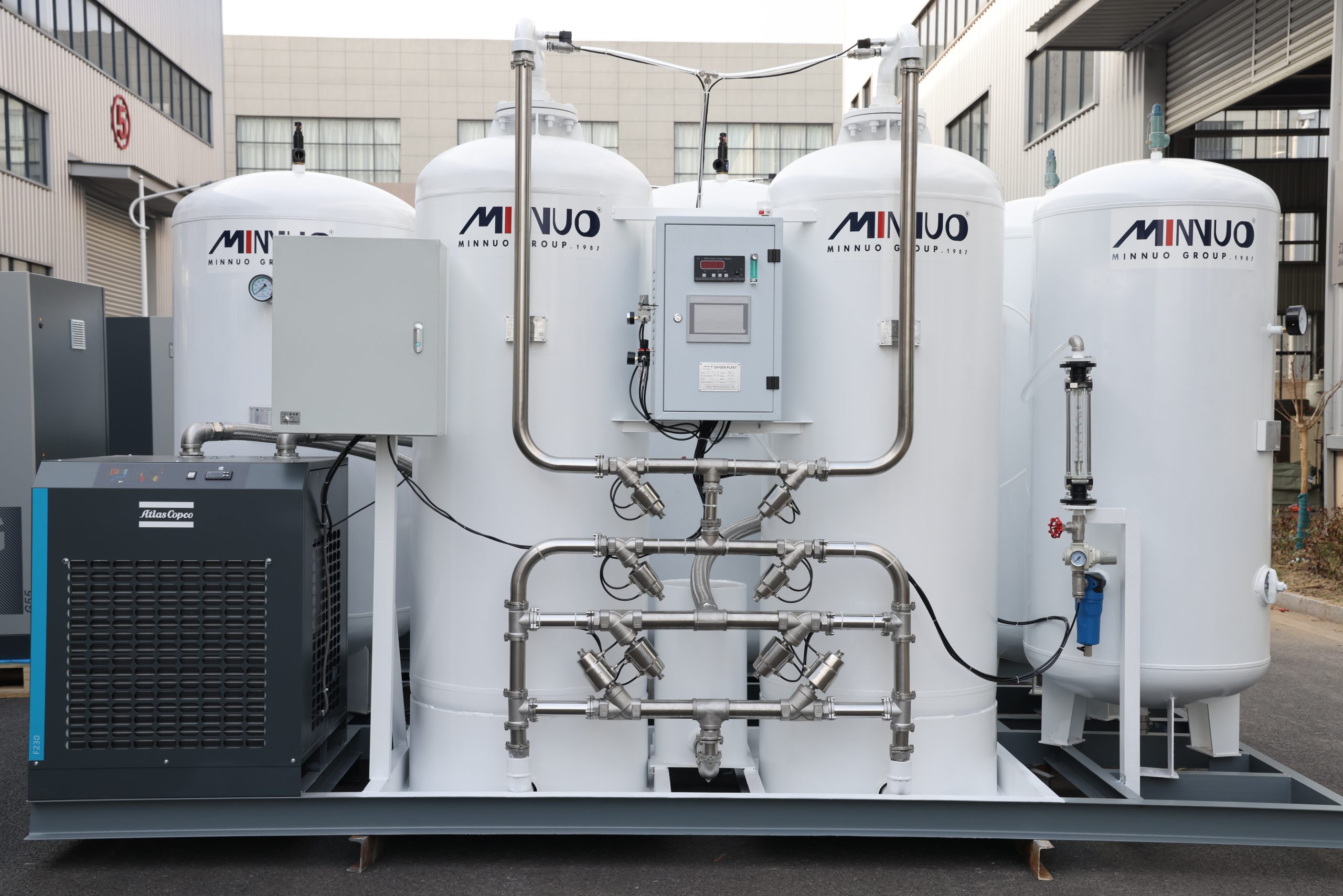
If you want to address these issues at their root and purchase high-quality membrane nitrogen generation equipment, please choose MINNUO.



 sales2:+86 17506119168

