In modern industry, nitrogen and oxygen piping systems are widely used, especially in the fields of manufacturing, medical treatment, and chemical industry, where the design and operational efficiency of gas delivery and gas piping systems directly affects production efficiency and safety. The accurate delivery of nitrogen and oxygen not only requires scientific design methods, but also relies on accurate flow calculations and pressure drop analysis, which are the basis for ensuring the stable and efficient operation of piping systems. Therefore, an in-depth understanding of how to perform flow and pressure drop calculations in nitrogen and oxygen piping systems is essential for optimizing gas delivery systems.
In this paper, we will detail how to perform flow and pressure drop calculations in nitrogen and oxygen piping systems to help engineers and technicians better understand these critical calculation processes. We will explore how to apply scientific formulas and standard tables for flow rate and pressure drop analysis based on factors such as gas characteristics, piping layout and operating conditions to ensure system efficiency and stability.
This article will provide readers with professional calculation methods and practical design tips to help them master how to calculate gas flow rate and pressure drop, as well as practical guidelines to further optimize the gas delivery system. It will reveal how to improve the system’s operating efficiency, reduce energy consumption and ensure a safe and stable gas supply through rational piping design and accurate flow calculations.
Ⅰ. Fundamentals of flow and pressure drop calculations
1. Basics of gas flow
1.1 Types of gas flow
Laminar flow: In the laminar flow state, gas molecules flow in an orderly manner along the pipe surface, which usually occurs in the case of lower flow velocity and narrower pipes. Laminar flow has a simple flow path and small friction loss, but its flow volume is limited.
Turbulence: Turbulence is a complex phenomenon in gas flow, manifested as an irregular flow state. Usually when the flow velocity is high or the pipe is thicker, the gas flow tends to be turbulent. Turbulence in the molecules are no longer orderly flow, resulting in greater energy loss.
Transitional flow: This is the transition from laminar to turbulent flow, where the flow velocity and piping conditions are between laminar and turbulent. Transitional flow usually causes instability to the system under certain conditions.
1.2 Mechanical Properties of Gas Flow
The mechanical properties of gas flow include, in addition to the type of gas, the roughness of the pipe, the temperature, density and pressure of the gas. These properties determine the flow rate and pressure drop of the gas in the pipe and the stability of its flow.
1.3 Ideal Gas Law and Flow Calculations
Fluid flow calculations often rely on the ideal gas law to derive flow rates. According to the ideal gas law, the flow rate of a gas can be calculated in a simplified manner by means of an equation of state. With this equation, specific values of flow rate can be deduced for a given temperature, pressure and gas type, which can help in the design of suitable pipe sizes.
2. Basic Theory of Flow Calculations
2.1 Continuity Equation
The law of conservation of mass requires that the flow rate of a gas be constant across any section of a pipe. That is, if the pipe becomes narrower, the flow rate will increase; if the pipe becomes wider, the flow rate will decrease. This equation plays a fundamental role in flow calculations. By using the flow equation, the amount of gas passing through the pipe per unit of time can be calculated.
2.2 Principles of Fluid Mechanics
Flow calculations are usually carried out on the basis of the principles of fluid mechanics, where the flow rate is influenced by mechanical parameters, including the diameter of the pipe, the viscosity of the fluid and the gas flow rate.
2.2.1 Bernoulli’s equation and flow calculation
Bernoulli’s equation is a very basic equation in fluid mechanics, which expresses the relationship between kinetic energy, potential energy and pressure energy when the fluid flows in the pipe. The equation is essential for flow calculations and pressure drop estimation, especially when the fluid flow rate and pressure in the pipe vary. Bernoulli’s equation holds in the ideal case where no viscous losses are considered:
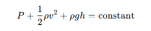
Where:
P is the pressure of the fluid
ρ is the density of the fluid
v is the velocity of flow
g is the acceleration of gravity
h is the height of the fluid
For flow calculation, Bernoulli’s equation helps to analyze the difference in velocity and pressure of the fluid at different pipe sections. Through this equation, we can derive the flow rate of the fluid at different locations and thus calculate the flow rate indirectly.
In practical applications, it is usually necessary to combine with other equations (such as the Darcy-Weisbach equation) to comprehensively consider the friction loss in the pipeline, and Bernoulli’s equation helps us to understand the flow state under ideal conditions.
2.2.2 Reynolds number (Re) and flow state
Reynolds number is a dimensionless number used to determine whether a fluid flow is laminar, turbulent or transitional. Reynolds number has an important role in flow calculation, especially in predicting the type of flow is particularly critical. The formula for Reynolds number is as follows:
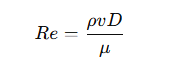
Where:
ρ is the density of the fluid
v is the flow rate
D is the diameter of the pipe
μ is the dynamic viscosity of the fluid
Typical flow classification of Reynolds number:
Laminar flow: Re<2000 applies to low-speed flow, at this time the fluid molecules according to the hierarchy of flow, the friction loss is small.
Turbulence: Re>4000 for high-speed flow, at this time the fluid molecules flow in disorder, friction loss is large, the flow state is not stable.
Transitional flow: 2000 < Re < 4000 in this range, the flow may be in between laminar and turbulent flow, the system may be disturbed.
Understanding the determination of Reynolds number for the flow state can help to decide if a different flow model needs to be used to calculate the flow rate and pressure drop.
2.3 Gas Flow Calculation Formulas
The flow calculation formulas are generally:
Calculation formula: Flow = Gas density × Velocity × Pipe cross-sectional area
In practice, flow measurements are adjusted by the gas equation of state taking into account several factors, such as temperature, pressure, and so on.
3. Fundamentals of pressure drop calculation
3.1 Influence of friction factor
The calculation of the friction factor is closely related to the flow state of the fluid (laminar, turbulent). In laminar flow, the friction factor is relatively small; whereas in turbulent flow, the friction factor increases, resulting in an increased pressure drop. The use of pipes with different materials and surface roughness affects the magnitude of the friction factor and thus the results of the pressure drop calculation.
3.2 Localized Losses
Localized losses are usually caused by valves, elbows, pipe connectors, etc. Each of these components causes a certain amount of pressure drop, which is usually calculated using empirical equations. These local loss calculations are essential to accurately estimate the overall pressure drop of the system.
4. Interrelationship of Pressure Drop and Flow
Flow and Pressure Drop: An increase in flow usually results in an increase in pressure drop because higher flow rates require more friction to be overcome. The design of the system needs to consider balancing the flow rate and pressure drop to ensure long term stable operation of the equipment.
Pressure drop and equipment efficiency: Excessive pressure drop may lead to a reduction in system efficiency or even increase energy consumption, so it must be reasonably calculated and designed to ensure that the pressure drop is controlled within the optimal range.
Ⅱ. Nitrogen and Oxygen Flow Calculation
Basic Principles of Flow Calculation:
Flow calculation is usually based on the equation of state of the gas and related physical properties. It is based on the principles of fluid mechanics, including the effects of pipe size, pressure, temperature, and other factors. By applying appropriate gas flow models and formulas, the flow rate of a gas can be calculated accurately and the gas piping system can be designed efficiently.
Flow rate formula:
The calculation of flow rate is one of the core of fluid dynamics. Flow formula based on the principles of fluid dynamics, can calculate the gas through the pipeline speed and volume flow.
Basic flow formula:
According to the state of gas flow, the flow formula can usually be expressed as:
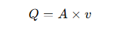
Where:
Q: gas flow rate (unit: Nm³/h or L/min)
A: cross-sectional area of the pipe (unit: m²)
v: gas flow rate (unit: m/s)
By calculating the flow rate, you can determine the flow rate value according to the size of the pipeline and the flow rate to ensure the effectiveness of the gas transportation system.
Practical application analysis:
In practical applications, it is crucial to know how to carry out flow calculations according to different operating conditions (e.g. pressure, temperature, etc.). For example, how to utilize standard tables or empirical formulas to adapt to changes in flow rates of different gas types (e.g., nitrogen or oxygen) to make precise adjustments in a gas delivery system.
Practical applications of flow calculation:
How to determine the flow rate according to different operating conditions:
In specific gas conveying systems (e.g. conversion of the flow rate in the labeled state to the actual state), the flow rate calculation must be adapted to the different operating conditions. Gases can change significantly in volume during transportation due to changes in temperature and pressure, so the flow rate calculation must take into account not only the initial conditions, but also changes in the actual operating environment.
How to ensure accurate measurement and adjustment of gas flow:
In actual pipeline design, accurate measurement of gas flow is crucial to ensure the stability of system operation. Through accurate flow calculation and selection of related equipment (e.g. flow meters, pressure sensors), the system can be effectively monitored to ensure a stable supply of nitrogen and oxygen flow.
III. Pressure Drop Calculation and Analysis
Friction Pressure Drop Calculation:
Friction pressure drop is the pressure loss due to the friction between the gas and the pipe wall as it flows through the pipe. It is one of the most common forms of pressure drop in gas transportation systems, especially in long pipelines, where friction pressure drop directly affects the gas flow rate, the energy efficiency of the system and the stability of the transportation.
Relationship between pipeline length and gas velocity:
Long pipelines: the gas flow rate is directly proportional to the length of the pipeline. The longer the pipeline, the greater the resistance to gas flow and the greater the pressure drop. Increasing the length of the pipeline will not only increase the friction pressure drop, but also increase the energy consumption, so the design of the pipeline needs to consider a reasonable length.
Gas velocity: the faster the flow rate, the greater the friction between the gas and the pipe wall, and the pressure drop increases. In practice, it is usually necessary to control the gas flow rate to avoid unnecessary energy loss caused by excessive pressure drop.
Formulas for Calculating Frictional Pressure Drop:
Commonly used formulas for calculating frictional pressure drop include the Darcy-Weisbach formula and the Colebrook formula. The Darcy-Weisbach formula is shown below:
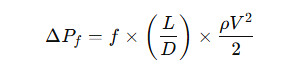
Where:
ΔPf: friction pressure drop (Pa)
f: friction factor (determined according to the Reynolds number and pipe roughness)
L: pipe length (m)
D: pipe diameter (m)
ρ: gas density (kg/m³)
V: gas flow rate (m/s)
The pressure drop of the gas due to friction in the pipeline can be calculated by the above formula.
How to use the relationship between friction factor and pipe material to calculate pressure drop:
Friction factor (f) is an important parameter affecting the friction pressure drop. Depending on the Reynolds number (Re) and the surface roughness of the pipe material, the appropriate friction factor can be selected. Common methods of calculating friction factor include the use of friction factor charts or formulas (e.g., Colebrook’s formula) to calculate the friction factor based on different flow regimes and pipe materials to determine the final pressure drop value.
Local Pressure Drop Calculations:
Local pressure drop refers to the pressure loss of a gas in a piping system as it passes through elbows, valves, filters, nozzles, and other equipment due to a change in flow direction or flow rate.
Connection parts between equipment and piping:
Valves: Valves regulate the flow rate by changing the flow path of the fluid, but it generates local resistance, which leads to pressure drop.
Elbows: The presence of elbows in piping causes a change in the direction of gas flow, which can also cause localized pressure drops.
Filters: The design and use of filters increases the resistance to fluid flow, which in turn creates a localized pressure drop.
The formula for calculating localized pressure drop:
Localized pressure drop is usually calculated by the following formula:
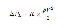
Where:
ΔPL: local pressure drop (Pa)
K: local resistance coefficient (different according to the type and size of equipment)
ρ: gas density (kg/m³)
V: gas flow rate (m/s)
The influence of local pressure drop mainly depends on the layout and design of all kinds of equipments in the piping system, so reasonable planning of piping system, avoiding excessive elbows, valves and other equipments, can effectively reduce the local pressure drop.
Practical application cases:
Gas piping design:
When designing gas piping, the friction pressure drop can be effectively controlled by reasonably choosing the diameter and length of the piping, the gas flow rate and the piping material.
Comparison with traditional materials and designs:
By comparing with piping systems of traditional materials and designs, optimized gas piping design can significantly reduce pressure drop, improve gas conveying efficiency and reduce energy consumption.
Ⅳ. Factors Affecting Flow and Pressure Drop Calculations
In gas flow and pressure drop calculations, there are multiple factors that can affect the flow and pressure drop of a gas. Understanding these factors is critical to the design and optimization of piping systems. They not only affect the efficiency of gas delivery, but may also determine the energy consumption and operational stability of the system. The following are some of the key factors:
Gas Properties:
The physical properties of the gas, such as the density, viscosity and temperature of the gas, play a vital role in flow and pressure drop calculations.
Density: The density of a gas directly affects its inertia and resistance to flow. Denser gases (e.g. oxygen) will have a larger pressure drop at the same flow rate.
Viscosity: The viscosity of a gas affects the resistance to flow of the gas in the pipeline.
Temperature: Temperature has a significant effect on the density and viscosity of gases. Higher temperature gases have a lower density and lower viscosity, which may lead to higher flow rates, but may also increase friction and localized pressure drops.
Pipe Characteristics:
The diameter, length, material, and surface roughness of the pipe also have a direct effect on flow rate and pressure drop.
Pipe Diameter: The larger the diameter of the pipe, the lower the flow rate of the gas and therefore the frictional pressure drop will be relatively small. Smaller pipe diameters increase the flow rate and friction, thus increasing the pressure drop. When designing, the appropriate pipe diameter should be selected based on a balance of flow requirements and piping costs.
Pipe Length: The longer the length of the pipe, the greater the resistance to gas flow, which leads to an increase in pressure drop. Therefore, when designing a gas conveying system, minimizing the length of the pipe can effectively reduce the pressure drop.
Pipe material: Different pipe materials (e.g. steel pipe, plastic pipe, etc.) have different effects on the resistance to gas flow. The smoothness and corrosion resistance of the material directly affects the friction coefficient of the inner surface of the pipe, thus affecting the pressure drop.
Pipe surface roughness: The roughness of the inner surface of the pipe affects the stability of the gas flow and friction, and a rough pipe surface increases the resistance to flow, which leads to a higher pressure drop.
Flow characteristics:
Flow characteristics are an important factor in determining gas flow and pressure drop.
Laminar vs. Turbulent: In a pipeline, gas flow can be laminar (lower velocity) or turbulent (higher velocity). In laminar flow, the flow is more stable and the pressure drop is smaller, while in turbulent flow, the gas flow becomes unstable and the frictional pressure drop is larger. An increase in flow velocity usually causes the gas flow to become turbulent, thus increasing the pressure drop.
Changes in flow rate: Changes in the flow rate of the gas directly affect the pressure drop in the pipeline. The higher the flow rate, the greater the friction between the gas and the pipe, resulting in an increase in pressure drop. Therefore, flow rates need to be precisely controlled during design to ensure efficient and economical gas transfer.
Temperature and pressure variations:
Temperature and pressure variations also play an important role in gas flow and pressure drop.
Effect of temperature changes: Changes in temperature affect the viscosity and density of the gas, which in turn affects the flow rate and pressure drop. Higher temperatures typically result in less dense and less viscous gases, which may reduce resistance to flow; the opposite is true for lower temperatures. Fluctuations in gas temperature need to be taken into account when designing a gas system, especially when operating in extreme temperature conditions.
The effect of pressure changes: Pressure changes in gases directly affect their density, and therefore resistance to flow and pressure drop. Gas molecules are more compact and have higher friction at high pressures, while the opposite is true at low pressures. Pressure regulation and control is the key to ensure stable gas flow and reasonable pressure drop.
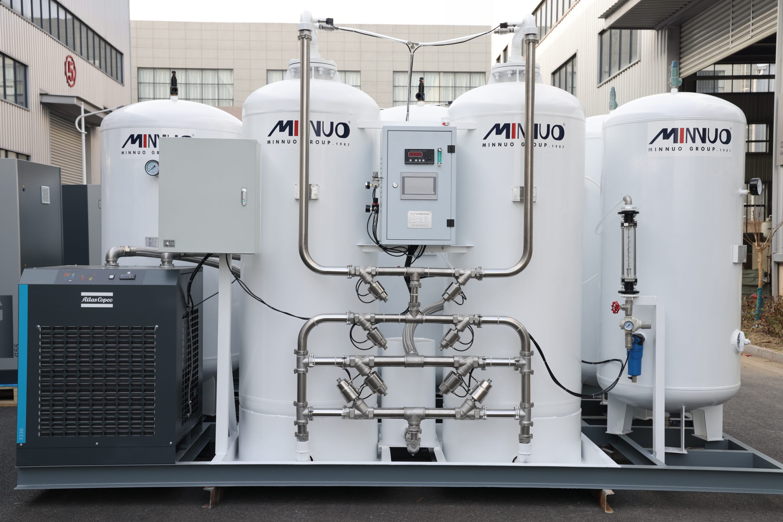
The PSA nitrogen generator is a core equipment that achieves efficient nitrogen production through pressure changes. Its operation process revolves around the cycle of “pressurized adsorption – depression-reduced desorption”, and it is necessary to precisely control the temperature and pressure parameters. The equipment usually has two adsorption towers working alternately, and is combined with a PLC control system to monitor key parameters such as pressure, temperature, and nitrogen purity, ensuring continuous and stable nitrogen production Excessively high temperatures will reduce the adsorption capacity of carbon molecular sieves, while pressure fluctuations will affect the separation efficiency and energy consumption.
Conclusion
This paper comprehensively explains how to perform flow and pressure drop calculations in nitrogen and oxygen piping systems, emphasizing the critical role of flow and pressure drop in system design and operational efficiency. Reasonable pipeline design and optimization calculations can not only improve the stability of gas delivery, but also reduce energy consumption and operating costs, thereby improving overall production efficiency. In the design of gas piping systems, the accurate calculation of flow rate and pressure drop is crucial to ensure the long-term stable operation of the system.
This article provides insights into how to calculate gas flow and pressure drop, and optimize piping design and equipment configuration to improve system performance. At the same time, MINNUO oxygen and nitrogen equipment, with its highly efficient and stable PSA technology, provides customized nitrogen and oxygen solutions for various industries, helping companies to better meet their gas needs and achieve efficient, energy-saving, and low-cost production processes.


 sales2:+86 17506119168