Membrane nitrogen technology, with its efficiency, stability, and convenience, has become an indispensable key gas solution in high-end fields such as petroleum extraction, chemical production, and electronics manufacturing. As a global leader in membrane nitrogen technology, MINNUO understands that professional and precise installation is the cornerstone for the efficient operation and extended lifespan of the equipment. This guide consolidates the extensive experience of MINNUO’s global engineering team, providing you with a comprehensive, step-by-step analysis covering everything from site selection to commissioning, and from maintenance to optimization. This ensures the perfect deployment of your membrane nitrogen generation system, enabling it to achieve maximum performance.
Key steps for installing a membrane nitrogen generation system include:
- Selecting a suitable installation site: Ensure the ground is level with good ventilation, avoiding high temperature, humidity, and harmful gases.
- Ensuring safety compliance: Wear Personal Protective Equipment (PPE) and conduct fire safety and electrical safety checks.
- Equipment handling and positioning: Follow procedures for moving and positioning the equipment, meticulously leveling it, and connecting piping and electrical systems to ensure sealing integrity and correct electrical connections.
- Commissioning checks: Inspect system operation, test nitrogen purity and flow stability during commissioning.
- Implementing regular maintenance: Conduct periodic cleaning of filters and inspection of equipment status to ensure long-term, efficient operation.
I. Critical Pre-Installation Preparations: Laying the Foundation for Safety and Efficiency
1.1 Scientific Site Selection and Rigorous Environmental Assessment
- Ground Load-Bearing Capacity and Levelness: A concrete foundation with a minimum grade of ≥C25 and thickness ≥150mm is preferred. The load-bearing capacity must significantly exceed the operating weight of the equipment (including full-load conditions). Use a high-precision level (laser level recommended) for multi-point inspection, ensuring the overall inclination is strictly ≤0.5° (approx. 1.7mm/m). Any minor unevenness can cause uneven airflow distribution within the membrane module, leading to stress concentration, significantly shortening membrane life and reducing separation efficiency.
- Ventilation, Heat Dissipation, and Space Layout:
- Air Circulation: The site must have good natural or forced ventilation to ensure timely dissipation of heat generated during operation. Relative humidity should be consistently ≤80% to prevent condensation damage to electrical components and membrane performance.
- Operation and Maintenance Space: Reserve ≥1.5 meters of clear, unobstructed space around the perimeter of the equipment and ≥1 meter of height above it. This ensures convenience and safety for daily inspections, filter element replacement, membrane module maintenance, and emergency handling.
- Temperature Control: Ambient temperature must be strictly controlled within the 5°C to 40°C range. For every 10°C increase in temperature, membrane permeability may increase by 15-25%, directly causing a decline in nitrogen purity. High-temperature environments (>40°C) significantly accelerate the aging and degradation process of polymeric membrane materials.
- Environmental Risk Avoidance:
- Strictly prohibit installation near sources of flammable/explosive materials (fuels, chemicals), high-concentration dust (e.g., coal dust, metal powder), or highly corrosive gases (e.g., chlorine, hydrogen sulfide).
- Avoid direct sunlight (UV damage) and direct exposure to rain/snow. Outdoor installation is strongly discouraged. If operational conditions necessitate outdoor placement, a fully enclosed, weatherproof shelter must be constructed, with consideration for extreme weather protection (typhoons, blizzards).
1.2 Comprehensive Safety and Compliance Preparation: The Bottom Line for Life and Regulations
- Personal Protective Equipment (PPE) Mandatory Requirements: All personnel involved must wear: ANSI Z87.1 certified impact-resistant safety glasses, wear-resistant, anti-slip heavy-duty rubber gloves, and GB21148-2020 standard steel-toe/cap anti-impact and anti-puncture safety boots. For any work at height (e.g., overhead piping connection), a full-body safety harness compliant with GB6095-2021 must be worn and connected to a reliable anchor point.
- On-Site Safety Facility Configuration:
- Display prominent warning signs (“No Smoking/Open Flames,” “High Voltage Danger,” “Must be Grounded”) at obvious locations on the equipment and on the power control cabinet.
- Based on site area and risk level, equip sufficient (typically ≥2 units) and correctly typed (ABC dry chemical fire extinguishers) firefighting equipment, ensuring they are within their validity period and easily accessible.
- Regulatory and Standards Compliance Review:
- Electrical Safety: Carefully verify and strictly adhere to the local electrical installation codes (e.g., China’s GB 50168, GB 50169; Europe’s IEC 60364). Confirm power supply voltage (380V±10%), frequency (50Hz±2%), and phase sequence are correct.
- Pressure Vessels and Piping: If the system includes pressure vessels (e.g., buffer tanks), confirm they possess a valid “Special Equipment Use Registration Certificate” and periodic inspection reports. Pipe welding and installation must comply with pressure piping codes such as ASME B31.3 or GB/T 20801.
- Explosion-Proof Requirements: If the installation area is classified as an explosive hazardous area (e.g., oil platform, chemical plant), all electrical equipment (motors, control cabinets, sensors, junction boxes) must hold ATEX (2014/34/EU) or IECEx explosion-proof certification corresponding to the zone classification (e.g., Zone 1, Zone 2), and installation must strictly follow explosion-proof installation codes (e.g., IEC 60079-14).
1.3 Equipment and Component Unpacking Verification: Eliminating Risks at the Source
- Unpacking Inspection: Unpack jointly with the supplier representative or carrier present. Record the entire unpacking process using a high-definition device (e.g., mobile phone). Verify items against the packing list: Focus on checking core components: membrane separation module (inspect shell for dents, intact interface threads), precision filter housings and elements (confirm model, quantity, packaging integrity), control system (PLC/touchscreen, instrument panel integrity), valves, and pipe fittings (model, material, quantity). Meticulously inspect for transport damage: Pay special attention to the equipment base, lifting points, precision instruments, and membrane module casing for impact, deformation, paint peeling, or water ingress. If any issues are found, photograph them immediately as evidence and contact MINNUO technical support and the logistics provider.
- Documentation Verification: Ensure receipt of the complete document package: Detailed Operation & Maintenance Manual (Chinese & English), Electrical Schematic and Wiring Diagram, Piping and Instrumentation Diagram (P&ID), Pressure Vessel Product Qualification Certificate, Certificate of Quality, Inspection Certificate (if applicable), Material Reports and Performance Test Reports for key components (e.g., membrane). Verify the equipment serial number matches the documentation.
II. Detailed Step-by-Step Installation Procedure: Precise Execution Every Step
2.1 Step 1: Safe Equipment Transportation and Precise Positioning
- Professional Handling: Use only the dedicated lifting points or forklift pockets clearly marked on the equipment casing. Lifting must utilize slings or dedicated lifting gear with sufficient rated load capacity (≥1.5 times equipment weight). Never hook pipes or instruments directly. When using a forklift, ensure the forks fully extend under the equipment base, and move slowly and steadily to prevent tipping or slipping. Immediately lock all wheel brakes after positioning wheeled equipment.
- Precise Positioning and Leveling: Move the equipment steadily to the pre-prepared foundation. Use a high-precision frame level or electronic level to measure at least 4 key points on the equipment base (front, back, left, right). Adjust by precisely inserting stainless steel leveling shims of varying thicknesses between the equipment base and the foundation, repeating adjustments until the level error at all measurement points is strictly ≤0.5°. This is a core prerequisite for ensuring long membrane module life and high-efficiency separation.
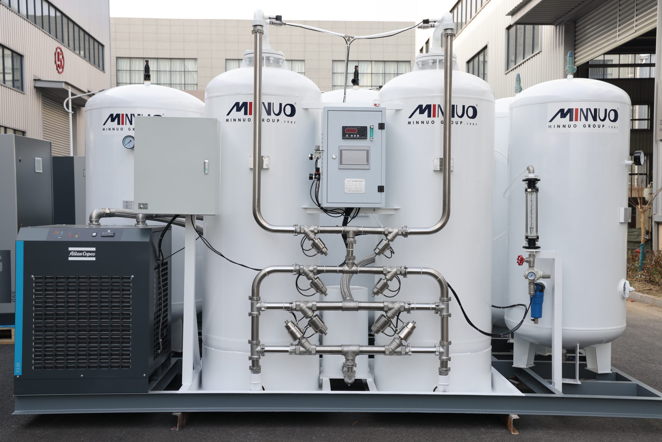
2.2 Step 2: System Piping Connection: Sealing and Cleanliness are Vital
- Compressed Air Supply Piping (Lifeblood):
- Source Connection: Connect the air compressor outlet to the membrane separation system inlet using thoroughly degreased, cleaned, and purged high-quality 304/316 stainless steel seamless pipe or pressure-resistant (≥1.6MPa) imported brand oil-resistant composite hose. Pipe diameter must be ≥ the equipment inlet diameter to avoid excessive throttling pressure drop.
- Three-Stage Filtration System (Core Safeguard):
- Pre-Filter: Installed after the air compressor to remove liquid water and large particles (filtration rating ≥3μm).
- Refrigerated Air Dryer: Lowers compressed air dew point to 3-10°C, removing significant water vapor.
- Precision Filter: Installed in series (e.g., C-grade main line filter + T-grade coalescing filter), ultimately ensuring air entering the membrane module has oil content ≤0.001ppm w/w (well below the 0.003ppm requirement) and solid particles ≤0.01μm. This is absolutely critical for protecting the expensive membrane module!
- Piping Construction: All threaded connections must be wrapped with high-quality PTFE tape (15-20 wraps along the thread direction) or coated with dedicated thread sealant (e.g., LOCTITE 577). Flanged connections require pressure-rated non-asbestos gaskets, with bolts tightened evenly and diagonally.
- Nitrogen Output Piping (Product Delivery):
- Buffering and Flow Stabilization: The nitrogen outlet must connect to a nitrogen buffer tank with a volume ≥1.5 times the system’s peak flow rate (Nm³/h). E.g., a 100 Nm³/h system requires a ≥150L tank. The tank should be equipped with a safety valve (set pressure at 1.1x working pressure), pressure gauge, and drain valve.Pipe Material: Recommend using internally/externally polished (BA/EP grade) stainless steel pipe to prevent contamination of high-purity nitrogen. Welding must use automatic TIG (argon arc welding) with 100% borescope inspection to ensure no weld beads or oxidation.Leak Test (Mandatory Requirement): After all piping connections are complete, pressure testing and leak testing must be performed:
- Pressure Test: Use clean, oil-free compressed air or nitrogen, slowly raise pressure to 1.5 times design pressure, hold for at least 30 minutes. Check all welds, joints, and valve packings for visible deformation or leakage.Leak Test: Reduce pressure to design pressure, apply high-sensitivity bubble solution (e.g., Snoop) to all joints – absolutely no bubbles must form. Hold pressure for ≥24 hours; pressure drop must comply with standards (e.g., ≤1%/hour).
- Buffering and Flow Stabilization: The nitrogen outlet must connect to a nitrogen buffer tank with a volume ≥1.5 times the system’s peak flow rate (Nm³/h). E.g., a 100 Nm³/h system requires a ≥150L tank. The tank should be equipped with a safety valve (set pressure at 1.1x working pressure), pressure gauge, and drain valve.Pipe Material: Recommend using internally/externally polished (BA/EP grade) stainless steel pipe to prevent contamination of high-purity nitrogen. Welding must use automatic TIG (argon arc welding) with 100% borescope inspection to ensure no weld beads or oxidation.Leak Test (Mandatory Requirement): After all piping connections are complete, pressure testing and leak testing must be performed:
- Exhaust System (Safe Emission): Route the oxygen-enriched exhaust gas (approx. 35-45% O2) generated by the membrane module via a dedicated pipe to an open, well-ventilated outdoor location at the upwind side, away from personnel activity areas and ignition sources. Fit the pipe end with a weather hood and protective screen. Strictly prohibit direct discharge in confined or poorly ventilated spaces due to the severe risk of oxygen depletion and suffocation!
2.3 Step 3: Electrical and Control System Precise Connection: The Intelligent Core
- Power Connection: Perform strictly according to electrical drawings by certified electricians. Use copper core cables compliant with national (e.g., BVR) or international (e.g., THHN) standards; wire gauge must meet the equipment’s full-load current requirements with adequate margin (typically ≥1.25 times calculated current). Grounding is paramount: Use an independent grounding electrode (e.g., copper-clad rod), ensure grounding wire gauge is sufficient (≥ phase wire gauge), and grounding resistance must be ≤4Ω (measured value). This is the fundamental safeguard against electric shock and equipment damage.
- Control System Installation and Initial Setup: Connect all sensors (pressure transmitters, temperature sensors, flow meters, oxygen analyzer signal cables) correctly to designated PLC/controller ports, using shielded twisted pair cable with the shield grounded at one end only. Power On Initialization: Upon first power-up, enter the PLC/touchscreen system.
- Key Parameter Setting:
- Target Nitrogen Purity: Set according to application (e.g., ≥99.999% for electronics inerting, ≥95% for oilfield nitrogen injection).Flow High/Low Alarm Limits.Filter Automatic Drain Cycle and Duration (e.g., drain solenoid valve activates for 5-10 seconds every 30 minutes of operation).Membrane Module Temperature Alarm Threshold (e.g., >45°C alarm).Pressure Protection Values (Low Pressure Shutdown, Overpressure Relief).
- Key Parameter Setting:
2.4 Step 4: Initial Commissioning and Performance Verification: Witnessing Efficiency
- Pre-Startup Cold Checks: Manually rotate the air compressor motor fan several turns, confirming absolutely smooth rotation without jamming or abnormal noise. Check all valve positions: Ensure inlet valve OPEN, exhaust valve OPEN (initial state), nitrogen product valve OPEN.
- No-Load Run Test: Start the air compressor, observe system pressure gauges. Pressure should stabilize within the 0.7~1.2MPa range (refer to equipment nameplate). Low pressure affects nitrogen production rate; high pressure may damage membrane fibers. Monitor Filters: Record the inlet/outlet pressure differential across each filter stage. Initial pressure drop across the coalescing filter should be ≤0.02MPa. If pressure drop across any stage approaches or exceeds 0.05MPa, it indicates severe filter clogging or installation issues – immediately shut down for inspection and replacement. Check if automatic drain valves activate normally according to the set cycle.
- Load Operation and Performance Verification:
- Purity Adjustment: Slowly close (or adjust) the exhaust valve (oxygen-enriched waste gas valve) to increase membrane module operating pressure. This process must be performed extremely slowly and steadily.
- Purity Measurement: Use a metrologically calibrated portable oxygen analyzer (accuracy better than ±0.1% O2) to monitor purity in real-time at the nitrogen outlet sampling point. Calibrate against online instrument readings (if available).
- Flow Stability Test: At the set purity level, record the flow meter reading for at least 1 hour. Flow fluctuation should be ≤±5% of the setpoint. Excessive fluctuation may stem from unstable air source pressure, insufficient buffer tank volume, or valve adjustment issues.
- System Interlock Test: Simulate alarm conditions like purity drop, abnormal pressure, high filter differential pressure, etc., to verify if the PLC accurately triggers audible/visual alarms and preset protective actions (e.g., auto-switchover, shutdown).
III. Post-Installation Scientific Maintenance and Continuous Optimization: Ensuring Long-Term Excellence
3.1 Daily Maintenance Routine: Nip Problems in the Bud
- Per Shift:
- Drain condensate from all filters and buffer tank bottoms (manually or confirm auto-drain is functioning).
- Visually inspect pressure, temperature, and flow meter readings are within normal ranges.
- Listen for abnormal operating sounds (air compressor, motors).
- Sniff for unusual odors (e.g., overheating, oil smell).
- Weekly:
- Use professional oil detection tubes or instruments to test inlet compressed air oil content, ensuring ≤0.001ppm.
- Check pipes and joints for visible leaks (listen, feel, apply bubble solution).
- Clean dust and oil from equipment exterior surfaces.
- Monthly:
- After power-off, thoroughly clean accumulated dust inside the electrical control cabinet and on cooling fan grilles using dry compressed air or a soft brush to prevent overheating damage due to poor heat dissipation.
- Check electrical terminals for looseness or overheating/discoloration signs (must be done by electrician).
- Verify alarm and interlock functions are effective.
3.2 Key Component Preventive Maintenance: Core to Extending Lifespan
- Membrane Separation Module (Core Asset of System): Every 6 months: Record nitrogen purity or permeate flow rate under identical operating pressure, flow rate, and temperature conditions. Calculate the membrane’s permeability decay rate. If the annual decay rate consistently exceeds >10% (e.g., >5% over six months), it indicates membrane contamination or physical damage; contact MINNUO technical support immediately for professional diagnosis and cleaning (never use chemical solvents yourself!). Regular cleaning can restore most performance.
- Filter Elements (Frontline Guardians):
- Coalescing Filter Element (T-grade): Replace strictly based on differential pressure or time (whichever comes first). Typically replace every 2000 operating hours or differential pressure ≥0.07MPa. Activated carbon oil vapor removal elements (if configured) also require replacement every 2000 hours, as their adsorption capacity saturates over time, leading to oil vapor breakthrough that poisons membranes, even if differential pressure is low.
- Main Line Filter Element (C-grade): Replace based on differential pressure (typically ≥0.05MPa) or every 4000 hours.
3.3 Long-Term Shutdown Protection: Safeguarding During Dormancy
If equipment is planned to be shut down for over 1 month, professional protection must be implemented:
- Complete Depressurization & Draining: Close inlet valves, open all drain valves, exhaust valve, and nitrogen outlet valve to completely empty the system of compressed air and condensate.
- Nitrogen Purging & Purging: Flush all piping and the membrane module interior thoroughly with dry, clean nitrogen (dew point ≤-40°C) to drive out moisture.
- Nitrogen Blanketing Seal: Close all valves and fill the system (especially the membrane module interior) with low-pressure (approx. 0.2-0.3MPa) dry nitrogen for sealing, preventing air (containing oxygen, water vapor) from entering.
- Power Disconnect & Dust Protection: Disconnect the main power switch. Cover the entire equipment completely with a dust and moisture-proof cover.
- Periodic Checks: Monthly, check the seal pressure; if pressure drops significantly, replenish nitrogen and locate the leak point.
IV. MINNUO Membrane Nitrogen Systems: Empowering Core Industrial Applications
4.1 Oilfield Enhanced Recovery & Safety Assurance:
- Case Study: SINOPEC Tahe Oilfield
- Challenge: Ultra-deep heavy oil (high viscosity), difficult conventional extraction, low efficiency.Solution: Deployed MINNUO high-capacity (>3000 Nm³/h), ultra-high pressure (70MPa) membrane nitrogen systems combined with coiled tubing for nitrogen lift and foam flooding.Results:
- Significantly reduced crude oil viscosity and improved flowability.Increased reservoir energy, enhancing recovery rates.Achieved well production increase exceeding 15%, significantly shortening the investment payback period.Replaced traditional liquid nitrogen trucks, reducing costs and improving operational flexibility and safety.
- Challenge: Ultra-deep heavy oil (high viscosity), difficult conventional extraction, low efficiency.Solution: Deployed MINNUO high-capacity (>3000 Nm³/h), ultra-high pressure (70MPa) membrane nitrogen systems combined with coiled tubing for nitrogen lift and foam flooding.Results:
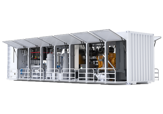
4.2 Mobile Vehicle-Mounted Emergency Nitrogen Generation: Flexible, Efficient, Mission Critical
- MINNUO Solution:
- Highly Integrated Design: Integrates oil-free air compressor, high-efficiency membrane modules, booster pump unit (optional), and intelligent control system onto a heavy-duty truck or standard shipping container.
- Robust Performance: Adapts to rugged off-road terrain, enabling rapid deployment to accident sites (blowouts, fires) or remote well sites.
- Core Value: Provides immediate, large volumes of high-purity nitrogen for well control (purging, well killing), pipeline purging, inerting protection, and emergency firefighting, maximizing personnel safety and minimizing property loss.
4.3 Electronics Industry Ultra-High Purity Protective Gas: Guardian of Precision Manufacturing
- Technical Requirements: Extremely demanding requirements for nitrogen purity (99.999%+), very low dew point (-60°C to -70°C), and oil-free/particle-free status (≤0.01μm, Class 0).
- MINNUO Technology Assurance:
- Utilizes special-grade polymeric separation membranes and multi-stage deep purification processes (combining high-efficiency oxygen removal, adsorption drying, terminal ultrafiltration).Provides stable and reliable nitrogen gas, widely used in:
- SMT Reflow/Wave Soldering: Prevents solder joint oxidation, improving yield.Semiconductor Chip Packaging & Testing: Creates an oxygen-free environment to prevent oxidation failure of sensitive components.LCD/OLED Panel Production: Protects precision coating processes.Laser Cutting/Welding Protection: Improves cut quality and reduces heat-affected zone.
- Utilizes special-grade polymeric separation membranes and multi-stage deep purification processes (combining high-efficiency oxygen removal, adsorption drying, terminal ultrafiltration).Provides stable and reliable nitrogen gas, widely used in:
V. Deep Dive into Common Questions (FAQ): Clearing Doubts
Q1: How long does the installation process typically take?
- Small Standard Systems (≤100 Nm³/h): With site fully prepared and proficient personnel, foundational positioning, piping connection, electrical wiring, and preliminary commissioning can be completed within 4-6 hours. The full process (including stringent pipe pressure testing, pressure holding, and final performance acceptance) typically requires 1 working day.
- Large/Custom Systems (>100 Nm³/h) or Complex Conditions: Involves more module assembly, large buffer tank installation, complex external piping runs, explosion-proof special requirements, etc. Installation and commissioning time typically requires 2-5 working days, depending on the specific site assessment.
Q2: What is the actual lifespan of the membrane modules and what are the key influencing factors?
- Expected Lifespan: Under strict adherence to operating specifications, inlet air quality compliance, and regular professional maintenance, MINNUO membrane modules have a design service life of 5-8 years.
- The Killer – Oil Contamination: If inlet air oil content is consistently or momentarily exceeded (>0.01ppm), oil molecules irreversibly clog membrane micropores and damage the material structure, causing a sharp decline in performance. Lifespan may be reduced to 2-3 years or less.
- Monitoring Recommendation: Perform professional membrane performance testing (purity/flow decay rate assessment) at least annually. Contact MINNUO promptly for diagnosis and cleaning upon noticeable performance decline.
Q3: What specific damage does installing the equipment tilted cause?
- Uneven Fiber Stress: Tilting causes thousands of long, thin hollow fiber membranes inside the module to bend, stretch, or compress unevenly under gravity.
- Serious Consequences:
- Accelerated Physical Aging and Breakage: Localized stress concentration significantly increases the risk of fiber breakage.
- Disrupted Flow Distribution: Affects uniform airflow distribution through the membrane bundle, creating “short-circuits” or “dead zones.”
- Significant Drop in Separation Efficiency: Effective membrane area is reduced, lowering both nitrogen purity and production rate.
- Conclusion: Level installation is a rigid requirement!
Q4: What if the ambient temperature consistently exceeds 40°C?
- Immediate Action: High temperature is the “natural enemy” of membrane performance.
- Solutions:
- Physical Cooling (Preferred): Install industrial air conditioning or high-power ventilation fans to forcibly reduce the ambient temperature around the equipment below 40°C.
- Relocate Equipment: If feasible, move the entire equipment to an air-conditioned indoor space or a cool, ventilated area.
- Water Cooling (Special Design): For specific models or extreme environments, custom-integrated or external water coolers can be employed to directly cool the compressed air entering the membrane module.
- Consequence of Inaction: Membrane permeability increases drastically, nitrogen purity becomes unattainable, membrane lifespan is significantly shortened.
Q5: Can the system be expanded if future production capacity needs increase?
- MINNUO’s Modular Advantage: Yes! MINNUO systems utilize a highly modular design.
- Expansion Method: You can increase the total nitrogen production capacity by adding membrane separation modules in parallel.
- Critical Prerequisites:
- Auxiliary Capacity Match: The capacity and discharge pressure of the front-end air compressor(s) must be simultaneously evaluated and upgraded to meet the flow and pressure requirements of the additional membrane module(s).Control System Upgrade: PLC I/O point expansion or controller software upgrade may be needed to manage additional modules.
- Pipe Sizing Review: Check if main piping (especially the main inlet header) diameter can handle the increased flow post-expansion to avoid becoming a bottleneck.
- Recommendation: Before expanding, always contact MINNUO technical support for a customized expansion plan evaluation report.
Q6: How to systematically troubleshoot sudden or sustained insufficient nitrogen purity?
Investigate step-by-step in priority order:
- Inlet Pressure: Is the air compressor functioning? Is the pressure gauge reading ≥ the equipment’s required minimum operating pressure (typically 0.7MPa)? Low pressure is the most common cause of purity deficiency.
- Filter Status: Check the differential pressure across all precision filter stages. If differential pressure on any stage ≥0.07MPa, it indicates severe clogging or failure – immediate replacement is mandatory. Check if automatic drains are functioning correctly.
- Membrane Module Temperature: Check ambient temperature and membrane module casing temperature. If >45°C, implement Q4 solutions. High temperature directly reduces membrane selectivity.
- System Leaks: Carefully check intake piping, membrane module casing, joints, valve stems, etc., using bubble solution for leaks. Leaks introduce untreated air.
- Exhaust Valve Opening: Check if the exhaust valve (oxygen-enriched waste gas valve) is mistakenly opened too wide? Excessive opening reduces membrane module operating pressure.
- Oxygen Analyzer Calibration: Confirm the accuracy of the online oxygen analyzer reading? Validate against a calibrated portable oxygen analyzer.
- Membrane Performance Degradation: If all the above are normal, the membrane module itself may be degrading due to aging or contamination. Contact MINNUO for professional testing and cleaning evaluation.
VI. Conclusion
As your trusted global partner, MINNUO not only provides world-leading membrane nitrogen generation equipment but is also committed to sharing decades of accumulated engineering experience and best practices through this comprehensive guide. For customized on-site installation assessments, professional technical guidance, or efficient after-sales service, MINNUO’s international technical support team is ready to assist. Contact us immediately to receive project-specific optimization advice and complete support tailored just for you!


 sales2:+86 17506119168