
Installing an interference fit bearing with a hydraulic press risks galling, misalignment, and component damage. Heating the housing works for some applications, but many assemblies cannot tolerate the temperatures required or the oxidation that accompanies heating. Liquid nitrogen shrink fitting solves both problems. By cooling the inner component to -196°C, the part contracts enough to slide effortlessly into its mating bore. When it warms to room temperature, it expands to create a permanent, precise interference fit—without force, without heat, and without damage. This guide explains how to perform liquid nitrogen shrink fitting safely and effectively.
I. The Physics Behind Shrink Fitting
Understanding thermal contraction enables accurate prediction of dimensional changes.
1. Thermal Contraction Fundamentals
All materials change dimensions with temperature. Cooling causes contraction; heating causes expansion. The amount of dimensional change depends on three factors:
- Initial dimension of the part
- Temperature change (ΔT)
- Material’s coefficient of thermal expansion
2. Coefficient of Thermal Expansion for Common Materials
| Material | Coefficient (μm/m/°C) | Contraction per 25mm at -196°C |
| Carbon steel | 11.7 | 0.064 mm |
| Stainless steel (304) | 17.3 | 0.095 mm |
| Stainless steel (316) | 16.0 | 0.088 mm |
| Aluminum (6061) | 23.6 | 0.130 mm |
| Brass | 18.7 | 0.103 mm |
| Bronze | 18.0 | 0.099 mm |
| Copper | 16.5 | 0.091 mm |
| Cast iron | 10.8 | 0.059 mm |
3. Calculating Dimensional Change
The formula for thermal contraction is:
ΔL = α × L₀ × ΔT
Where:
- ΔL = Change in dimension (mm or inches)
- α = Coefficient of thermal expansion
- L₀ = Initial dimension at room temperature
- ΔT = Temperature change (room temperature to -196°C = approximately -220°C)
Example calculation for a 50mm diameter steel shaft:
- α = 11.7 × 10⁻⁶ /°C
- L₀ = 50 mm
- ΔT = -220°C (from 24°C to -196°C)
- ΔL = 11.7×10⁻⁶ × 50 × (-220) = -0.129 mm
The 50mm shaft will contract to approximately 49.87mm in liquid nitrogen—providing 0.13mm of clearance for assembly.
4. Why Shrink Fitting Beats Press Fitting
| Parameter | Press Fitting | Shrink Fitting |
| Risk of galling | High | None |
| Alignment precision | Difficult to maintain | Self-aligning during insertion |
| Force required | High (tons of pressure) | Zero (gravity or light hand pressure) |
| Surface damage risk | Moderate to high | None |
| Suitable for thin-walled parts | No (distortion risk) | Yes |
| Equipment cost | Press required | LN2 dewar only |
II. Required Equipment and Materials
Proper tools ensure safe, effective shrink fitting operations.
1. Liquid Nitrogen Supply and Containment
| Item | Purpose | Specification |
| Liquid nitrogen dewar | LN2 storage and dispensing | 10-50 liter portable dewar |
| Cryogenic container | Part immersion vessel | Stainless steel or specialized plastic |
| LN2 transfer hose | Safe transfer from dewar | Vacuum-jacketed or foam-insulated |
| Level indicator | Monitor LN2 level in container | Dipstick or electronic sensor |
2. Part Handling Tools
Never handle cryogenic-temperature parts with bare hands or standard tools.
| Tool | Purpose | Material |
| Cryogenic gloves | Hand protection | Loose-fitting, waterproof cryo-rated |
| Long-handled tongs | Retrieve parts from LN2 | Stainless steel |
| Lifting hooks/eyes | Suspend parts during cooling | Steel with insulated handle |
| Guide rods/pins | Align parts during assembly | Brass or aluminum |
3. Personal Protective Equipment
| PPE Item | Requirement |
| Face shield | Full-face protection (over safety glasses) |
| Cryogenic gloves | Loose-fitting, extends over wrists |
| Cryogenic apron | Leather or non-porous material |
| Safety footwear | Closed-toe, chemical-resistant |
| Long sleeves/pants | No cuffs to trap liquid |
4. Optional but Recommended Equipment
- Infrared thermometer: Verify part temperature before assembly
- Oxygen monitor: For enclosed workspaces (alarm at 19.5% O₂)
- Ventilation fan: Ensure adequate air exchange
- Heating blanket or lamp: Accelerate part warm-up after assembly
III. Step-by-Step Shrink Fitting Procedure
Follow this sequence for consistent, damage-free results.
Step 1: Verify Interference Fit Dimensions
Before cooling any part, confirm the interference amount is appropriate for shrink fitting:
- Measure both parts at room temperature using calibrated micrometers
- Calculate interference: Bore diameter minus shaft/outer diameter (negative value = interference)
- Verify clearance after cooling: Calculated contraction must exceed interference by at least 0.025mm (0.001 inch) for easy assembly
Example verification:
- Bearing outer diameter at 24°C: 50.025 mm
- Housing bore at 24°C: 50.000 mm
- Interference: 0.025 mm
- Calculated contraction at -196°C: 0.129 mm
- Clearance after cooling: 0.129 – 0.025 = 0.104 mm (sufficient)
Step 2: Prepare the Mating Part
The part remaining at room temperature should be clean, dry, and ready to receive the cooled component.
- Clean bore thoroughly with solvent; remove all oil, grease, and debris
- Apply thin film of recommended lubricant if specified (some applications require dry assembly)
- Position housing for vertical insertion if possible (gravity assists alignment)
- Have alignment tools and guide pins ready
Step 3: Cool the Component in Liquid Nitrogen
- Fill cryogenic container with sufficient LN2 to fully submerge the part
- Lower part slowly into LN2 using tongs or suspension wire (rapid immersion causes thermal shock)
- Allow part to cool until boiling subsides—this indicates the part has reached LN2 temperature
- Typical cooling times:
| Part Mass | Approximate Cooling Time |
| <1 kg | 5-10 minutes |
| 1-5 kg | 10-20 minutes |
| 5-20 kg | 20-40 minutes |
| >20 kg | 40+ minutes |
- Part is ready when LN2 boiling around it reduces to gentle simmer
Step 4: Execute the Assembly
This step must be performed quickly once the part leaves LN2—warming begins immediately.
- Remove part from LN2 using appropriate handling tools
- Do not delay: Transfer to assembly position in one smooth motion
- Align part carefully with bore (use guide pins if available)
- Insert with steady, gentle pressure—do not hammer or force
- If part binds, remove immediately before it warms and expands
Step 5: Allow Natural Warm-Up
- Let assembly warm to room temperature naturally
- Do not apply external heat to accelerate warming (thermal shock risk)
- Warm-up time depends on part mass—typically 30 minutes to 2 hours
- Verify part is fully seated once temperature equalizes
- Check final position against reference marks or dimensions
Step 6: Post-Assembly Inspection
- Verify correct seating depth and alignment
- Check for any signs of cracking or distress
- Perform functional rotation test if applicable
- Document assembly for quality records
IV. Safety Protocols for Liquid Nitrogen Shrink Fitting
Liquid nitrogen presents unique hazards that require specific controls.
1. Cryogenic Burn Prevention
LN2 at -196°C causes instantaneous freezing of skin and severe tissue damage.
- Never handle LN2 or cooled parts with bare hands —even briefly
- Wear loose-fitting cryogenic gloves (tight gloves trap LN2 against skin)
- Inspect gloves before each use; replace if damaged or contaminated with oil/grease
- Remove watches, rings, and jewelry before handling LN2
2. Oxygen Enrichment and Asphyxiation
LN2 vaporizes to nitrogen gas, displacing oxygen in enclosed spaces.
- Perform shrink fitting in well-ventilated areas —never in confined spaces without monitoring
- Install oxygen monitor if workspace has limited ventilation
- Alarm setpoint: 19.5% O₂ (normal air is 20.9%)
- If dizziness or shortness of breath occurs, evacuate immediately
3. Liquid Oxygen Condensation
Uninsulated LN2 lines and containers condense oxygen from air. Liquid oxygen is a severe fire and explosion hazard.
- Do not leave LN2 in open containers for extended periods
- Keep oil, grease, and combustibles away from LN2 equipment
- Clean all tools and containers of oil before LN2 contact
- If blue liquid (liquid oxygen) is observed, stop work and evacuate area
4. Material Embrittlement Risk
Some materials become brittle at cryogenic temperatures.
| Material | Cryogenic Suitability |
| Carbon steel | Good (suitable) |
| Stainless steel (304/316) | Excellent |
| Aluminum alloys | Excellent |
| Brass/bronze | Good |
| Cast iron | Caution (may crack if cooled unevenly) |
| Plastics (most) | Poor (embrittlement) |
| Carbon fiber composites | Poor (matrix cracking) |
5. Pressure Buildup in Closed Cavities
Parts with blind holes or closed cavities can trap LN2, which expands 700:1 upon vaporization.
- Ensure all cavities are vented before LN2 immersion
- Drill vent holes if necessary (consult engineering)
- Never seal a part that has been immersed in LN2 until fully warmed
V. Common Applications for Liquid Nitrogen Shrink Fitting
1. Bearing Installation
Ball and roller bearings with interference fits on shafts or in housings are ideal candidates. Shrink fitting eliminates brinelling damage from press fitting and ensures square seating.
2. Bushing and Sleeve Assembly
Bronze bushings in steel housings, valve guides in cylinder heads, and wear sleeves on shafts—all assemble cleanly with LN2 shrink fitting.
3. Dowel Pin and Alignment Pin Installation
Precision dowels requiring light interference for accurate location benefit from shrink fitting, which preserves hole geometry and pin straightness.
4. Gear and Sprocket Mounting
Gears with interference bores mount on shafts without keyway damage or hub cracking. Particularly valuable for hardened gears susceptible to press-fit stress.
5. Shrink Fitting of Shaft Couplings
Large industrial couplings with interference fits assemble without heat distortion or the massive hydraulic forces required for press fitting.
6. Repair and Remanufacturing
Worn shafts restored with shrink-fit sleeves, bearing journals rebuilt with interference rings—LN2 shrink fitting enables precision repairs without welding or machining to size.
VI. Troubleshooting Common Problems
| Problem | Possible Cause | Solution |
| Part won’t enter bore | Insufficient cooling or excessive interference | Verify interference calculation; cool part longer |
| Part binds halfway | Uneven warming, misalignment | Remove immediately; restart with guide pins |
| Part cracks during cooling | Thermal shock, material unsuitability | Warm part more gradually; verify material compatibility |
| Frost formation prevents handling | Normal—LN2 cools surrounding air | Use tongs; frost does not affect assembly |
| Part seizes before fully seated | Inadequate clearance, slow assembly | Remove immediately; re-cool and try faster insertion |
| Condensation after assembly | Normal—cold part condenses humidity | Allow to dry naturally; apply light oil if corrosion concern |
FAQ
Q1: How long can I leave a part in liquid nitrogen?
A1: Indefinitely. LN2 cooling does not damage suitable materials regardless of duration. Once boiling subsides, the part is at LN2 temperature and ready for use. Extended soaking provides no additional dimensional change.
Q2: Can I reuse liquid nitrogen after shrink fitting?
A2: Yes. LN2 remaining in the cryogenic container can be used for additional parts. However, do not return LN2 to the storage dewar—contamination risk is too high. Use leftover LN2 for additional cooling operations or allow to evaporate safely.
Q3: What is the minimum interference suitable for shrink fitting?
A3: Shrink fitting works for any interference that provides positive clearance after cooling. For small parts (<25mm diameter), interferences as low as 0.005-0.010mm are practical. The limiting factor is assembly speed—very small clearances require faster assembly before warming reduces clearance.
Q4: Can I shrink fit parts with different materials?
A4: Yes, and this is common. For example, a steel shaft in an aluminum housing. Calculate contraction based on the part being cooled (the steel shaft in this case). The housing remains at room temperature. Differential thermal expansion is the principle behind shrink fitting.
Q5: How do I know if my part is suitable for cryogenic cooling?
A5: Most metals are suitable. Avoid cooling:
- Plastics and polymers (embrittlement)
- Carbon fiber composites (matrix cracking)
- Parts with hardened surfaces and sharp corners (stress risers)
- Parts with welded sections (differential contraction stresses)
When in doubt, consult material supplier or test with non-critical part first.
Q6: What size liquid nitrogen dewar do I need for occasional shrink fitting?
A6: A 10-20 liter portable dewar serves most occasional users. This size provides sufficient LN2 for multiple small-to-medium parts and stores for several days with minimal boil-off. Larger shops performing daily shrink fitting should consider 50-160 liter containers with dispensing hoses.
Conclusion
Liquid nitrogen shrink fitting provides a clean, damage-free method for assembling interference fit components. The physics is straightforward—cooling to -196°C provides sufficient contraction for most practical interferences. Success depends on accurate pre-assembly measurement, proper cooling time, swift and aligned insertion, and disciplined safety practices. When performed correctly, shrink fitting produces assemblies with full design interference and zero installation damage.
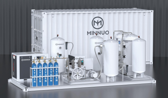
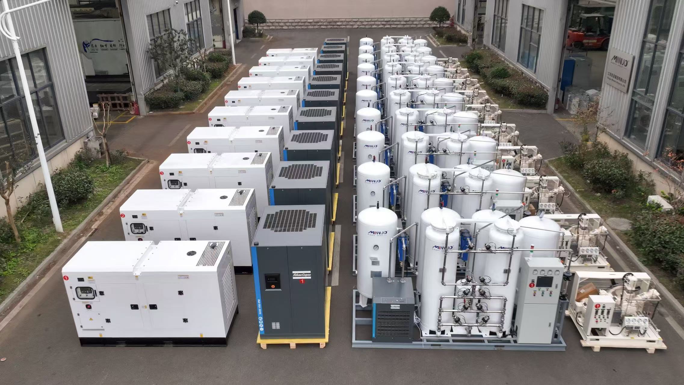
At MINNUO, we supply liquid nitrogen equipment and accessories for shrink fitting applications—including portable cryogenic dewars, LN2 transfer hoses, cryogenic gloves, and handling tools. Whether you operate a heavy equipment repair shop, a precision manufacturing line, or a field service operation, our cryogenic products support safe, reliable shrink fitting. Every MINNUO product meets industry standards for cryogenic service and includes documentation for workplace safety compliance. Contact our team to discuss your liquid nitrogen equipment requirements.

 sales2:+86 17506119168